Notice SOMFY 9020207 Electronique SOMFY FREEVIA
Produit concerné

FREEVIA
FR — Remplacement du boîtier électronique
EN — Replacing the electronic unit
PL — Wymiana modułu elektronicznego
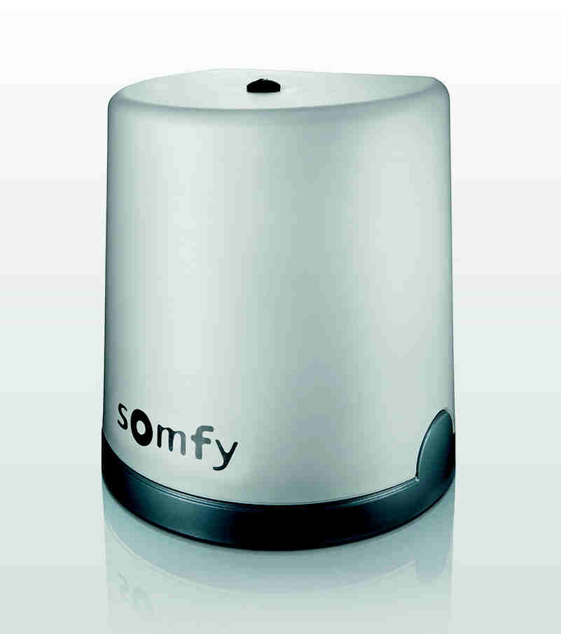
FR — Remplacement du boîtier électronique
Version originale du manuel. Ce manuel décrit le remplacement du boîtier électronique de votre motorisation et sa mise en service. Nous apportons régulièrement des améliorations à nos produits (câblage, paramétrage, etc.). Cette nouvelle électronique peut être différente de l'électronique d'origine de votre motorisation. Pour cette raison, VEUILLEZ SUIVRE ATTENTIVEMENT LA NOTICE FOURNIE AVEC VOTRE NOUVELLE ÉLECTRONIQUE.
Présentation de l'électronique de commande
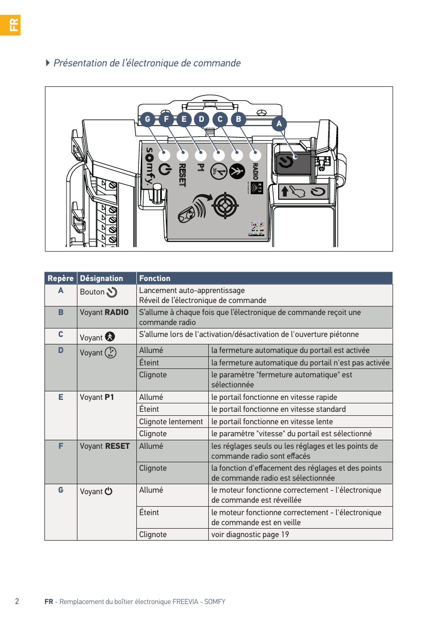
| Repère | Désignation | Fonction | |
|---|---|---|---|
| A | Bouton | Lancement auto-apprentissage ; Réveil de l'électronique de commande | |
| B | Voyant RADIO | S'allume à chaque fois que l'électronique de commande reçoit une commande radio | |
| C | Voyant | S'allume lors de l'activation/désactivation de l'ouverture piétonne | |
| D | Voyant | Allumé | la fermeture automatique du portail est activée |
| Éteint | la fermeture automatique du portail n'est pas activée | ||
| Clignote | le paramètre "fermeture automatique" est sélectionnée | ||
| E | Voyant P1 | Allumé | le portail fonctionne en vitesse rapide |
| Éteint | le portail fonctionne en vitesse standard | ||
| Clignote lentement | le portail fonctionne en vitesse lente | ||
| Clignote | le paramètre "vitesse" du portail est sélectionné | ||
| F | Voyant RESET | Allumé | les réglages seuls ou les réglages et les points de commande radio sont effacés |
| Clignote | la fonction d'effacement des réglages et des points de commande radio est sélectionnée | ||
| G | Voyant | Allumé | le moteur fonctionne correctement - l'électronique de commande est réveillée |
| Éteint | le moteur fonctionne correctement - l'électronique de commande est en veille | ||
| Clignote | voir diagnostic | ||
1 Remplacement du boîtier électronique
1.1 Installation du nouveau boîtier électronique
Pour votre sécurité, ces opérations doivent se faire hors tension.
- Mettre l'installation hors tension.
- Dévisser puis enlever le capot du moteur.
- Repérer le câble d'alimentation 230V et les câbles des périphériques.
- Installer et visser le nouveau boîtier électronique.
- Clipser l'antenne sur le dessus du moteur.
Tant qu'ils ne sont pas rebranchés, les fils des accessoires doivent rester isolés (par exemple avec des dominos d'électricien ou du scotch isolant) pour éviter tout risque de court-circuit.
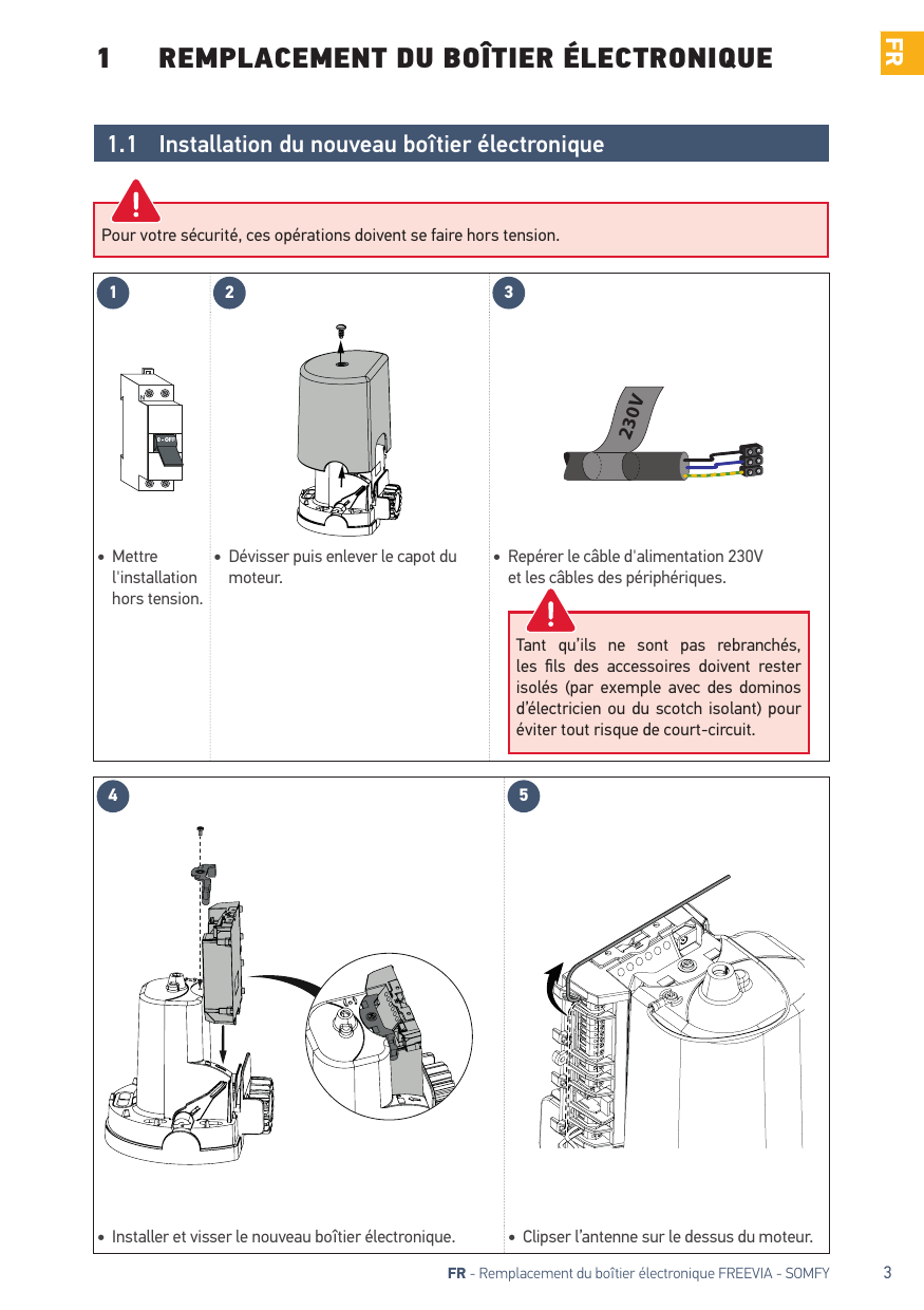
1.2 Câblage du moteur
Pour votre sécurité, ces opérations doivent se faire hors tension. Ne branchez rien sur la borne M2.
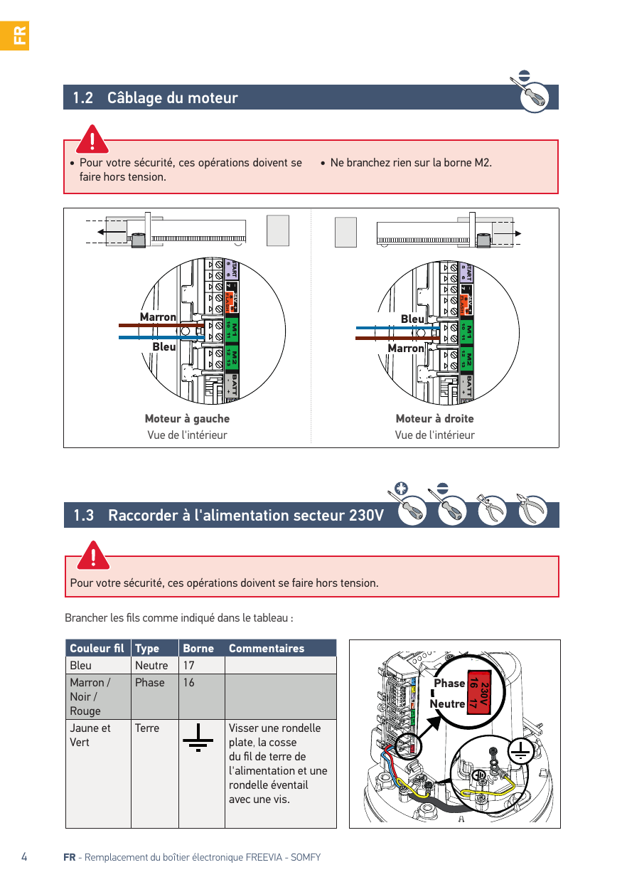
1.3 Raccorder à l'alimentation secteur 230V
Pour votre sécurité, ces opérations doivent se faire hors tension.
Brancher les fils comme indiqué dans le tableau :
| Couleur fil | Type | Borne | Commentaires |
|---|---|---|---|
| Bleu | Neutre | 17 | |
| Marron / Noir / Rouge | Phase | 16 | |
| Jaune et Vert | Terre | Visser une rondelle plate, la cosse du fil de terre de l'alimentation et une rondelle éventail avec une vis. |
1.4 Raccorder l'électronique de commande à la terre
- Raccorder le fil de terre fourni en haut à droite de l'électronique de commande.
- Visser une rondelle plate, la cosse du fil de terre et une rondelle éventail avec une vis sur le haut du moteur.
1.5 Déverrouillage du moteur
Mettre la poignée du moteur en position déverrouillée. Le pignon est libéré. Le moteur est déverrouillé.
1.6 Verrouillage du moteur
Ne verrouillez jamais le moteur lorsque le portail est en mouvement au risque de détériorer la motorisation.
Pousser la poignée du moteur vers le portail. Le moteur est verrouillé.
2 Mise en service et utilisation standard
2.1 Mettre l'installation sous tension
- Le voyant clignote (2 fois). Le moteur est sous tension et en attente d'auto-apprentissage.
- Si le voyant ne s'allume pas ou que le nombre de clignotements n'est pas celui attendu : voir diagnostic.
2.2 Enregistrer une télécommande 2 ou 4 touches
- Poser la télécommande à programmer sur la cible de l'électronique de commande.
- Faire un appui bref sur la touche de la télécommande à programmer. Le voyant "RADIO" s'allume puis s'éteint lorsque vous relâchez la touche de la télécommande. L'ouverture totale est programmée sur cette touche.
2.3 Auto-apprentissage de la course du portail
Pré-requis - Avant de lancer l'auto-apprentissage, vérifier que :
- L'installation est sous tension : le voyant clignote (2 fois).
- Le portail est à mi-course.
- Le moteur est verrouillé.
Appuyer sur le bouton de l'électronique de commande.
- Le portail s'ouvre, se ferme, s'ouvre partiellement et se ferme à nouveau.
- Le voyant s'allume fixe.
L'auto-apprentissage est réussi et le moteur est opérationnel. Si le voyant clignote (2 fois), recommencer l'auto-apprentissage. Le portail doit être fermé à la fin de l'auto-apprentissage. Si le portail est ouvert, voir encadré IMPORTANT ci-dessous.
IMPORTANT — Si le portail est ouvert à la fin de l'auto-apprentissage :
- Effacer les réglages.
- Mettre le moteur hors tension.
- Inverser les fils branchés sur les bornes 10 et 11 (étiquette verte M1) de l'électronique de commande (voir « Câblage du moteur »).
- Déverrouiller le moteur.
- Positionner le portail à mi-course.
- Verrouiller le moteur.
- Mettre le moteur sous tension.
- Recommencer l'auto-apprentissage.
Pendant l'auto-apprentissage, un appui sur la touche 1 de la télécommande ou sur le bouton de l'électronique de commande entraîne l'arrêt du portail et de l'auto-apprentissage.
2.4 Mise en veille / réveil de l'électronique de commande
Pour vérifier si le moteur est sous tension ou pour vérifier/modifier le paramétrage, appuyer 2 secondes sur le bouton pour réveiller l'électronique.
Lorsque l'auto-apprentissage a été effectué, l'électronique passe automatiquement en veille après 5 minutes d'inactivité, pour faire des économies d'énergie. En état de veille, tous les voyants sont éteints.
2.5 Monter le capot
- Placer le capot sur le moteur.
- Mettre en place le joint pour assurer l'étanchéité du moteur sur la vis du capot. Visser le capot.
3 Câblage des accessoires
Pour votre sécurité, ces opérations doivent se faire hors tension.
Il est conseillé de réaliser l'auto-apprentissage de la course du portail avant de raccorder les accessoires (cellules photoélectriques, feu orange, etc.)
3.1 Cellules photoélectriques
Le câblage d'un second jeu de cellules photoélectriques n'est pas possible sur cette motorisation.
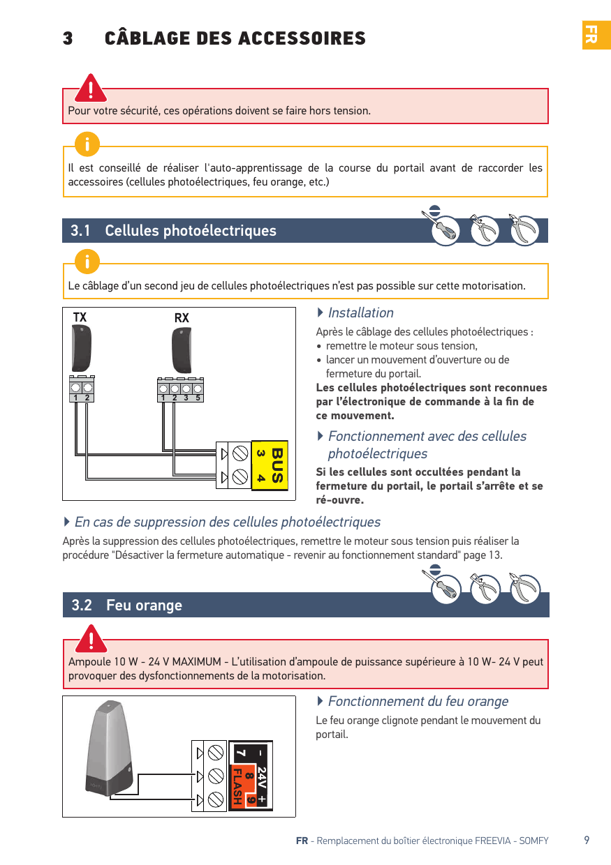
Installation. Après le câblage des cellules photoélectriques : remettre le moteur sous tension, lancer un mouvement d'ouverture ou de fermeture du portail. Les cellules photoélectriques sont reconnues par l'électronique de commande à la fin de ce mouvement.
Fonctionnement avec des cellules photoélectriques. Si les cellules sont occultées pendant la fermeture du portail, le portail s'arrête et se ré-ouvre.
En cas de suppression des cellules photoélectriques. Après la suppression des cellules photoélectriques, remettre le moteur sous tension puis réaliser la procédure "Désactiver la fermeture automatique - revenir au fonctionnement standard".
3.2 Feu orange
Ampoule 10 W - 24 V MAXIMUM - L'utilisation d'ampoule de puissance supérieure à 10 W- 24 V peut provoquer des dysfonctionnements de la motorisation.
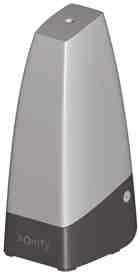
Fonctionnement du feu orange. Le feu orange clignote pendant le mouvement du portail.
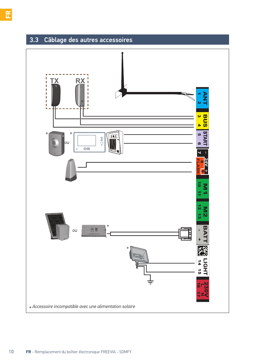
3.3 Câblage des autres accessoires
4 Paramétrages avancés
4.1 Ouverture piétonne
Fonctionnement de l'ouverture piétonne. Un appui sur la touche de la télécommande programmée pour l'ouverture piétonne entraîne une ouverture d'environ 1 mètre du portail. Un nouvel appui sur la touche referme le portail.
La touche 1 des télécommandes 2 ou 4 touches ne peut pas être programmée pour commander l'ouverture piétonne du portail.
Activer l'ouverture piétonne :
- Appuyer 2 s sur le bouton de l'électronique de commande. Le voyant s'allume.
- Poser la télécommande sur la cible de l'électronique de commande.
- Appuyer sur la touche 2 de la télécommande. Les voyants "RADIO" et s'allument puis s'éteignent. L'ouverture piétonne est activée sur cette touche.
Éloignez-vous de l'électronique de commande pour tester l'ouverture piétonne.
Désactiver l'ouverture piétonne. Répéter la procédure "Activer l'ouverture piétonne" avec la touche pour laquelle l'ouverture piétonne doit être désactivée. Le voyant s'allume puis s'éteint. L'ouverture piétonne est désactivée sur cette touche.
4.2 Fermeture automatique
Fonctionnement de la fermeture automatique. Appuyer sur la touche 1 de la télécommande pour ouvrir le portail. Le portail se referme après 30 secondes ou 5 secondes si un passage est détecté par les cellules photoélectriques. La fermeture automatique du portail peut être interrompue en appuyant sur la touche 1 de la télécommande. Pour ensuite refermer le portail, appuyer à nouveau sur la touche 1 de la télécommande.
La fermeture automatique ne peut être activée que si des cellules photoélectriques sont câblées et reconnues par l'électronique de commande du moteur.
Activer la fermeture automatique :
- Appuyer 2 s sur le bouton de l'électronique de commande. Le voyant s'allume.
- Poser la télécommande sur la cible de l'électronique de commande.
- Rester appuyé sur la touche 1 de la télécommande jusqu'à ce que le voyant clignote.
- Rester appuyé sur la touche 2 de la télécommande jusqu'à ce que le voyant s'éteigne puis s'allume fixe.
- Lorsque la touche 2 est relâchée, le voyant clignote, appuyer 3 fois sur la touche 1 de la télécommande. Le voyant reste allumé. La fermeture automatique est activée.
Désactiver la fermeture automatique - revenir au fonctionnement standard :
- Appuyer 2 s sur le bouton de l'électronique de commande. Le voyant s'allume.
- Poser la télécommande sur la cible de l'électronique de commande.
- Rester appuyé sur la touche 1 de la télécommande jusqu'à ce que le voyant clignote.
- Appuyer sur la touche 2 de la télécommande. Le voyant clignote.
- Appuyer 3 fois sur la touche 1 de la télécommande.
- Le voyant est éteint. La fermeture automatique est désactivée.
4.3 Vitesse du portail
Par défaut, le portail fonctionne en vitesse standard.
DANGER Tout changement de réglage de la vitesse du portail doit être réalisé par un installateur professionnel de la motorisation et de l'automatisation de l'habitat. Toutes modifications qui ne respectent pas ces instructions mettent en péril la sécurité des biens et des personnes.
Domaine d'application. Paramétrer la vitesse du portail suivant le tableau ci-dessous :
| Poids du portail | Vitesse rapide | Vitesse standard | Vitesse lente |
|---|---|---|---|
| 0 à <100 kg | Oui + barre palpeuse* | Oui | Oui |
| 100 à <200 kg | Oui + barre palpeuse* | Oui | Oui |
| 200 à <300 kg | Oui + barre palpeuse* | Oui + barre palpeuse* | Oui |
| 300 à <400 kg | Non | Oui + barre palpeuse* | Oui |
| 400 à <500 kg | Non | Non | Oui + barre palpeuse* |
| 500 à <600 kg | Non | Non | Oui + barre palpeuse* |
*Installation d'une barre palpeuse passive (ref. 9014597) sur le portail obligatoire.
AVERTISSEMENT Si le paramètre de vitesse est modifié, l'installateur doit impérativement vérifier que la détection d'obstacle est conforme à l'annexe A de la norme EN 12 453. Le non respect de cette consigne pourrait gravement blesser des personnes, par exemple écrasées par le portail.
Paramétrer la vitesse rapide ou lente :
- Appuyer 2 s sur le bouton de l'électronique de commande. Le voyant s'allume.
- Poser la télécommande sur la cible de l'électronique de commande.
- Rester appuyé sur la touche 1 de la télécommande jusqu'à ce que le voyant clignote.
- Appuyer une fois sur la touche 1 de la télécommande. Le voyant P1 clignote.
- Pour la vitesse lente : rester appuyé sur la touche 2 jusqu'à ce que le voyant P1 clignote lentement (la vitesse lente est sélectionnée). Pour la vitesse rapide : appuyer une fois sur la touche 2, le voyant P1 s'allume fixe 5 secondes puis clignote (la vitesse rapide est sélectionnée).
- Appuyer 2 fois sur la touche 1 de la télécommande. Pour la vitesse lente, le voyant P1 clignote lentement. Pour la vitesse rapide, le voyant P1 reste allumé.
Revenir à la vitesse standard :
- Appuyer 2 s sur le bouton de l'électronique de commande. Le voyant s'allume.
- Poser la télécommande sur la cible de l'électronique de commande.
- Rester appuyé sur la touche 1 de la télécommande jusqu'à ce que le voyant clignote.
- Appuyer une fois sur la touche 1 de la télécommande. Le voyant P1 clignote.
- Appuyer une fois sur la touche 2 de la télécommande. Le voyant P1 s'éteint 5 secondes puis clignote.
- Appuyer 2 fois sur la touche 1 de la télécommande. Le voyant P1 est éteint. La vitesse standard est sélectionnée.
5 Programmation des télécommandes
5.1 Ajouter une télécommande
- Appuyer 2 s sur le bouton de l'électronique de commande. Le voyant s'allume.
- Poser la télécommande à programmer sur la cible de l'électronique de commande.
- Faire un appui bref sur la touche de la télécommande à programmer. Le voyant "RADIO" s'allume puis s'éteint lorsque la touche de la télécommande est relâchée. L'ouverture totale est programmée sur cette touche.
5.2 Supprimer les télécommandes
Voir « Effacer les réglages ».
6 Dépannage
La motorisation doit être déconnectée de toute source d'alimentation durant le nettoyage, la maintenance et lors du remplacement des pièces.
6.1 Assistance
Si la panne persiste ou pour tout autre problème ou demande de renseignement sur votre motorisation, rendez-vous sur notre Forum d'entraide : forum.somfy.fr. La communauté est là pour vous répondre, et la réponse à votre question y figure peut être déjà ! Vous pouvez également prendre contact auprès d'un conseiller Somfy par téléphone au 0 820 055 055 (0.15€ la minute), disponibilité du service sur www.somfy.fr
6.2 Changer la pile de la télécommande
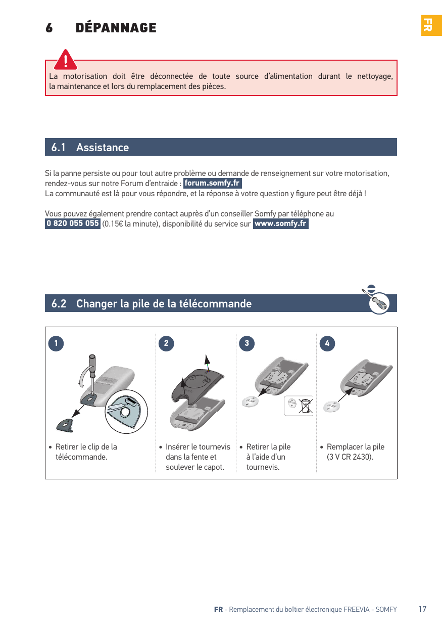
- Retirer le clip de la télécommande.
- Insérer le tournevis dans la fente et soulever le capot.
- Retirer la pile à l'aide d'un tournevis.
- Remplacer la pile (3 V CR 2430).
6.3 Effacer les réglages
Dans quels cas effacer les réglages ?
- Après l'auto-apprentissage, si vous changez la butée d'ouverture de position, si vous modifiez le câblage des moteurs ou si vous ajoutez une barre palpeuse sur le portail.
- En cas de réouvertures aléatoires du portail dues à une usure normale du portail.
- Appuyer 2 s sur le bouton de l'électronique de commande. Le voyant s'allume.
- Poser la télécommande mémorisée sur la cible.
- Rester appuyé sur la touche 1 de la télécommande jusqu'à ce que le voyant clignote.
- Appuyer 2 fois sur la touche 1 de la télécommande.
- Le voyant "RESET" clignote.
- Pour effacer les réglages* : rester appuyé sur la touche 2 de la télécommande jusqu'à ce que le voyant "RESET" s'allume. Pour effacer les réglages* et les télécommandes/points de commande mémorisés : rester appuyé sur la touche 2 de la télécommande jusqu'à ce que tous les voyants s'allument.
- Le voyant clignote 2 fois (pour lancer un auto-apprentissage).
*Course du portail, désactivation des paramètres, ...
6.4 Diagnostic
| Diagnostic | Cause | Dépannage |
|---|---|---|
| Le moteur ne répond pas aux commandes de la télécommande | Portée de la télécommande réduite | Vérifier la pile de la télécommande. Vérifier l'antenne du boîtier électronique (câblage, position). Vérifier qu'il n'y a pas d'élément extérieur susceptible de perturber les émissions radio (pylône électrique, murs ferraillés, etc.). Si tel est le cas, prévoir une antenne déportée. |
| Télécommande non mémorisée | Mémoriser la télécommande. | |
| Moteur déverrouillé | Verrouiller le moteur. | |
| Le voyant du boîtier électronique est éteint | L'électronique est en veille | Appuyer 2 secondes sur le bouton pour réveiller l'électronique. |
| Électronique de commande non alimentée | Vérifier l'alimentation secteur. Vérifier le câble d'alimentation. | |
| 1 clignotement | Fonctionnement sur batterie de secours | Vérifier l'alimentation secteur. |
| 2 clignotements | Moteur en attente d'apprentissage de la course du portail | Lancer l'auto-apprentissage. |
| 3 clignotements | Cellules photoélectriques en défaut | Vérifier qu'il n'y a pas d'obstacle entre les cellules. Vérifier l'alignement des cellules. Vérifier le câblage des cellules. Si les cellules sont volontairement débranchées, réaliser la procédure "Désactiver la fermeture automatique - revenir au fonctionnement standard". |
| 4 clignotements | Court-circuit sur "START" du boîtier électronique (bornes 5-6) | Vérifier les accessoires branchés sur "START" du boîtier électronique. |
| 5 clignotements | Sécurité thermique du moteur enclenchée | Laisser le moteur refroidir quelques dizaines de minutes. |
| 6 clignotements | Court-circuit sur "BUS" du boîtier électronique (bornes 3-4) | Vérifier les accessoires branchés sur "BUS" du boîtier électronique. |
| Court-circuit sur "24 V" du boîtier électronique (bornes 7-9) | Vérifier l'accessoire branché sur "24 V" du boîtier électronique. | |
| Court-circuit "feu orange" du boîtier électronique (bornes 8-9) | Vérifier le câblage du feu orange. | |
| Court-circuit moteur | Vérifier le câblage du moteur. | |
| 7 clignotements | Défaut électronique | Contacter l'assistance Somfy. |
7 Caractéristiques techniques
| Alimentation | 230 V-50 Hz / 24 V (en solaire) |
|---|---|
| Type de moteur | 24 V |
| Puissance du moteur | 120 W |
| Puissance maxi consommée (avec éclairage de zone) | 600 W |
| Consommation en veille | 3,5 W |
| Fréquence maximum de manoeuvres par jour | 20 cycles / jour ; 10 cycles / jour en solaire |
| Temps d'ouverture | 16 s pour un portail de 150 kg/3m |
| Détection d'obstacle automatique | Conforme à la norme EN 12 453 |
| Température de fonctionnement | -20°C à +60°C |
| Protection thermique | Oui |
| Indice de protection | IP 44 |
| Récepteur radio intégré | Oui |
| Télécommandes — Fréquence radio | 433,42 MHz, < 10 mW |
| Télécommandes — Portée en champ d'usage | ~ 30 m |
| Télécommandes — Quantité mémorisable | 16 |
| Sortie pour feu orange | Clignotante, 24 V, 10 W maximum |
| Sortie éclairage | 500 W maxi en 230 V (halogène ou incandescence uniquement) |
| Sortie alimentation accessoires | 24 Vdc / 15 W maxi |
| Entrée pour batterie de secours | Oui |
| Entrée pour cellules photoélectriques | Oui |
| Entrée de commande de type contact sec | Oui (ne fonctionne pas si alimentation batterie ou solaire) |
EN — Replacing the electronic unit
Translated version of the guide. This guide describes how to replace and commission the electronic unit of your drive. We make regular improvements to our products (wiring, parameter settings, etc.). These new electronics may differ from the original electronics of your drive. Consequently, PLEASE FOLLOW THE GUIDE PROVIDED CAREFULLY WITH YOUR NEW ELECTRONICS.
Presentation of the control electronics
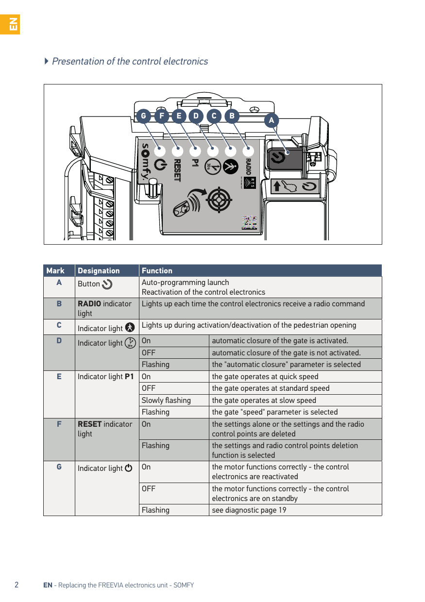
| Mark | Designation | Function | |
|---|---|---|---|
| A | Button | Auto-programming launch ; Reactivation of the control electronics | |
| B | RADIO indicator light | Lights up each time the control electronics receive a radio command | |
| C | Indicator light | Lights up during activation/deactivation of the pedestrian opening | |
| D | Indicator light | On | automatic closure of the gate is activated. |
| OFF | automatic closure of the gate is not activated. | ||
| Flashing | the "automatic closure" parameter is selected | ||
| E | Indicator light P1 | On | the gate operates at quick speed |
| OFF | the gate operates at standard speed | ||
| Slowly flashing | the gate operates at slow speed | ||
| Flashing | the gate "speed" parameter is selected | ||
| F | RESET indicator light | On | the settings alone or the settings and the radio control points are deleted |
| Flashing | the settings and radio control points deletion function is selected | ||
| G | Indicator light | On | the motor functions correctly - the control electronics are reactivated |
| OFF | the motor functions correctly - the control electronics are on standby | ||
| Flashing | see diagnostic | ||
1 Replacing the electronic unit
1.1 Installing the new electronic unit
For your safety, these operations must be carried out with the power supply switched off.
- Switch the installation off.
- Unscrew and remove the motor cover.
- Identify the 230V power supply cable and the peripherals cables.
- Install and screw the new electronic unit into place.
- Clip the aerial on top of the motor.
Until they are reconnected, the accessories wires must remain insulated (for example with a screw terminal or insulating tape) to avoid any risk of a short circuit.
1.2 Wiring the motor
For your safety, these operations must be carried out with the power supply switched off. Connect nothing to terminal M2.
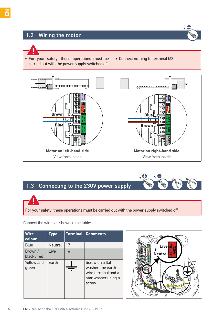
1.3 Connecting to the 230V power supply
For your safety, these operations must be carried out with the power supply switched off.
Connect the wires as shown in the table:
| Wire colour | Type | Terminal | Comments |
|---|---|---|---|
| Blue | Neutral | 17 | |
| Brown / black / red | Live | 16 | |
| Yellow and green | Earth | Screw on a flat washer, the earth wire terminal and a star washer using a screw. |
1.4 Earthing the control electronics
- Connect the earth wire supplied to the top right of the control electronics.
- Tighten a flat washer, the earth wire terminal and a star washer using a screw to the top of the motor.
1.5 Unlocking the motor
Position the motor's handle. The pinion is freed. The motor is unlocked.
1.6 Engaging the motor
Never lock the motor when the gate is moving as this may damage the drive.
Push the motor handle towards the gate. The motor is locked.
2 Commissioning and standard use
2.1 Switching the installation on
- The indicator flashes (twice). The motor is switched on and awaiting auto-programming.
- If the indicator light does not come on or the number of flashes is not as expected: see diagnostic.
2.2 Programming a 2- or 4-button remote control
- Position the remote control to be programmed on the control electronics target.
- Briefly press the button on the remote control to be programmed. The "RADIO" indicator light will come on then go out when you release the button on the remote control. Complete opening is programmed on this button.
2.3 Gate travel auto-programming
Prerequisite - before starting auto-programming, check that:
- The installation is switched on: the indicator light flashes (twice).
- The gate is at its mid-point.
- The motor is locked.
Press the button on the control electronics.
- The gate opens, closes, opens partially and closes again.
- The indicator light is lit constantly.
Auto-programming has been successfully completed and the motor is operational. If the indicator light flashes (twice), begin the auto-programming process again. The gate must be closed once auto-programming is complete. If the gate is open, see the IMPORTANT box below.
IMPORTANT — If the gate is open once auto-programming is complete:
- Clear the settings.
- Switch the motor off.
- Switch the wires connected to terminals 10 and 11 (green M1 label) of the control electronics (see "Motor wiring").
- Unlock the motor.
- Position the gate at its mid-point.
- Lock the motor.
- Switch the motor on.
- Starting the auto-programming process again.
During the auto-programming process, pressing button 1 on the remote control or the button on the control electronics causes the gate and the auto-programming process to stop.
2.4 Standby / reactivation of the control electronics
To check if the motor is switched on or to check/modify the parameter setting, press the button for 2 seconds to reactivate the electronics.
Once the auto-programming process has been completed, the electronics automatically switch to standby after 5 minutes of inactivity to save energy. In standby mode, all indicator lights are switched off.
2.5 Lifting the cover
- Place the cover on the motor.
- Insert the seal to ensure the motor and cover screw are watertight. Fasten the cover.
3 Wiring the accessories
For your safety, these operations must be carried out with the power supply switched off.
You are advised to perform auto-programming of the gate travel before connecting the accessories (photoelectric cells, orange light, etc.)
3.1 Photoelectric cells
It is not possible to connect a second set of photoelectric cells on this drive.
Installation. After wiring the photoelectric cells: switch the motor on again, start a gate opening or closing procedure. The photoelectric cells are recognised by the control electronics once this movement is complete.
Operation with photoelectric cells. If the cells are blocked when closing the gate, the gate will stop and reopen.
In the event of photoelectric cell disconnection. After disconnecting the photoelectric cells, switch the engine on again then perform the procedure "Deactivating automatic closing - returning to standard operation".
3.2 Orange light
10 W - 24 V bulb MAXIMUM - use of a bulb with power greater than 10 W- 24 V can cause drive malfunctions.
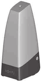
Operation of the orange light. The orange light flashes while the gate is moving.
3.3 Wiring the other accessories
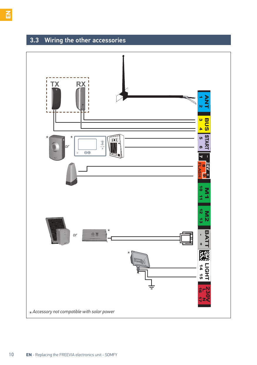
4 Advanced parameter settings
4.1 Pedestrian opening
Pedestrian opening operation. Pressing the remote control button programmed to open the pedestrian opening causes the gate to open about 1 metre. Pressing the button again, closes the gate.
Button 1 on 2- or 4-button remote controls cannot be programmed to control pedestrian opening.
Activating the pedestrian opening:
- Press the button on the control electronics for 2 seconds. The indicator light comes on.
- Position the remote control on the control electronics target.
- Press button 2 on the remote control. The "RADIO" and indicator lights come on then go out. The pedestrian opening is activated on this button.
Move away from the control electronics to test the pedestrian opening.
Deactivating the pedestrian opening. Repeat the "Activate pedestrian opening" procedure using the button for which the pedestrian opening must be deactivated. The indicator light comes on then goes out. The pedestrian opening is deactivated on this button.
4.2 Automatic closing
Automatic closure operation. Press button 1 on the remote control to open the gate. The gate closes again after 30 seconds or 5 seconds if the photoelectric cells detect a passage. The automatic closing can be interrupted by pressing button 1 on the remote control. To then close the gate, press button 1 on the remote control again.
The automatic closing can only be activated if the photoelectric cells are connected and recognised by the motor's control electronics.
Activating automatic closing:
- Press the button on the control electronics for 2 seconds. The indicator light comes on.
- Position the remote control on the control electronics target.
- Keep button 1 of the remote control depressed until the indicator light flashes.
- Keep button 2 on the remote control depressed until the indicator light goes out and is then lit constantly.
- When you release button 2, the indicator light flashes; press button 1 on the remote control 3 times. The indicator light remains lit. Automatic closing is activated.
Deactivating automatic closing - returning to standard operation:
- Press the button on the control electronics for 2 seconds. The indicator light comes on.
- Position the remote control on the control electronics target.
- Keep button 1 of the remote control depressed until the indicator light flashes.
- Press button 2 on the remote control. The indicator light flashes.
- Press button 1 on the remote control 3 times.
- The indicator light is off. Automatic closing is deactivated.
4.3 Gate speed
By default, the gate operates at standard speed.
DANGER Any change to the gate speed setting must be performed by a professional motor and home automation installer. Any changes which do not comply with these instructions represent a danger to the safety of both people and property.
Field of application. Set the gate speed in accordance with the table below:
| Gate weight | Quick speed | Standard speed | Slow speed |
|---|---|---|---|
| 0 to <100 kg | Yes + safety edge* | Yes | Yes |
| 100 to <200 kg | Yes + safety edge* | Yes | Yes |
| 200 to <300 kg | Yes + safety edge* | Yes + safety edge* | Yes |
| 300 to <400 kg | No | Yes + safety edge* | Yes |
| 400 to <500 kg | No | No | Yes + safety edge* |
| 500 to <600 kg | No | No | Yes + safety edge* |
*Installation of a passive safety edge (ref. 9014597) mandatory on the gate.
WARNING If the speed setting is changed, the installer must check that the obstacle detection system complies with appendix A of standard EN 12 453. Failure to follow these instructions could result in serious injury, e.g. crushing by the gate.
Quick or slow speed setting:
- Press the button on the control electronics for 2 seconds. The indicator light comes on.
- Position the remote control on the control electronics target.
- Keep button 1 of the remote control depressed until the indicator light flashes.
- Press button 1 on the remote control once. Indicator light P1 flashes.
- To set slow speed: keep button 2 depressed until the indicator light P1 flashes slowly (slow speed is selected). To set quick speed: press button 2 once, indicator light P1 will be lit for 5 seconds before flashing (quick speed is selected).
- Press button 1 on the remote control twice. For slow speed, indicator light P1 flashes slowly. For quick speed, indicator light P1 remains lit.
Returning to standard speed:
- Press the button on the control electronics for 2 seconds. The indicator light comes on.
- Position the remote control on the control electronics target.
- Keep button 1 of the remote control depressed until the indicator light flashes.
- Press button 1 on the remote control once. Indicator light P1 flashes.
- Press button 2 on the remote control once. Indicator light P1 goes out for 5 seconds then flashes.
- Press button 1 on the remote control twice. Indicator light P1 is off. Standard speed is selected.
5 Programming the remote controls
5.1 Adding a remote control
- Press the button on the control electronics for 2 seconds. The indicator light comes on.
- Position the remote control to be programmed on the control electronics target.
- Briefly press the button on the remote control to be programmed. The "RADIO" indicator light will come on then go out when you release the button on the remote control. Complete opening is programmed on this button.
5.2 Deleting a remote control
See "Clearing the settings".
6 Repairs
The drive must be disconnected from any power supply during cleaning, during maintenance and when parts are replaced.
6.1 Assistance
If the fault remains or for any other problem or enquiry relating to your drive, visit www.somfy.com
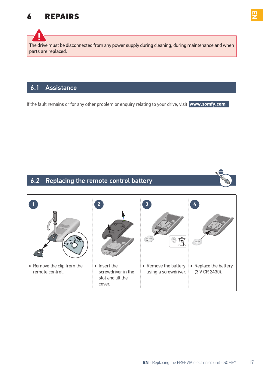
6.2 Replacing the remote control battery
- Remove the clip from the remote control.
- Insert the screwdriver in the slot and lift the cover.
- Remove the battery using a screwdriver.
- Replace the battery (3 V CR 2430).
6.3 Clear the settings
When should I delete the settings?
- After auto-programming, if you change the position opening stop, if you change the motor cables or if you add a safety edge to the gate.
- If the gate opens at random due to normal wear of the gate.
- Press the button on the control electronics for 2 seconds. The indicator light comes on.
- Place the memorised remote control on the target.
- Keep button 1 of the remote control depressed until the indicator light flashes.
- Press button 1 on the remote control twice.
- The "RESET" indicator light flashes.
- To clear the settings*: keep button 2 of the remote control depressed until the "RESET" indicator light comes on. To clear the settings* and the memorised remote controls/control points: keep button 2 of the remote control depressed until all the indicator lights come on.
- The indicator light flashes twice (to run a self-learning procedure).
*Gate travel, deactivation of the settings, ...
6.4 Diagnostics
| Diagnostics | Cause | Repairs |
|---|---|---|
| The motor does not respond to commands from the remote control | The remote control range is reduced | Check the remote control battery. Check the aerial of the electronics unit (wiring, position). Check that there are no outside elements that may be interfering with the radio signal (electric pylon, metal reinforced walls, etc.). If this is the case, fit an offset aerial. |
| Non-memorised remote control | Memorise the remote control. | |
| Motor unlocked | Lock the motor. | |
| The indicator light on the electronics unit is off | The electronics unit is on standby | Press for 2 seconds to reactivate the electronics unit. |
| No power supply to the control electronics | Check the mains power supply. Check the power supply cable. | |
| 1 flash | Operation using the backup battery | Check the mains power supply. |
| 2 flashes | Motor waiting for gate travel to be programmed | Start auto-programming procedure. |
| 3 flashes | Faulty photoelectric cells | Check that there is nothing obstructing the cells. Check cell alignment. Check the cell wiring. If the cells are deliberately disconnected, perform the procedure "Deactivating automatic closing - returning to standard operation". |
| 4 flashes | Short circuit of electronic unit "START" output (terminals 5-6) | Check the accessories connected to the electronic unit's "START" output. |
| 5 flashes | Motor thermal protection device activated | Allow the motor to cool down for several minutes. |
| 6 flashes | Short circuit of electronics unit's "BUS" output (terminals 3-4) | Check the accessories connected to the electronic unit's "BUS" output. |
| Short circuit of electronics unit's "24 V output" (terminals 7-9) | Check the accessory connected to the electronic unit's "24 V" output. | |
| Short circuit of electronics unit's "orange light" output (terminals 8-9) | Check the wiring of the orange light. | |
| Motor short circuit | Check the motor wiring. | |
| 7 flashes | Electrical fault | Contact Somfy assistance. |
7 Technical data
| Power supply | 230 V-50 Hz / 24 V (with solar power) |
|---|---|
| Motor type | 24 V |
| Motor output | 120 W |
| Max. power consumed (with area lighting) | 600 W |
| Standby consumption | 3.5 W |
| Maximum frequency of movements per day | 20 cycles per day ; 10 cycles per day using solar power |
| Opening time | 16 s for a gate of 150 kg/3m |
| Automatic obstacle detection | Compliant with standard EN 12 453 |
| Operating temperature | -20°C to +60°C |
| Thermal protection | Yes |
| Protection rating | IP 44 |
| Integrated radio receiver | Yes |
| Remote controls — Radio frequency | 433.42 MHz, < 10 mW |
| Remote controls — Range in field of use | ~30 m |
| Remote controls — Storage quantity | 16 |
| Output for orange light | Flashing, 24 V, 10 W maximum |
| Lighting output | 500 W max. with 230 V (halogen or incandescent only) |
| Accessories supply output | 24 Vdc / 15 W max. |
| Backup battery input | Yes |
| Photoelectric cell input | Yes |
| Dry contact control input | Yes (does not work with battery or solar power) |
PL — Wymiana modułu elektronicznego
Przetłumaczona wersja instrukcji. Instrukcja ta opisuje sposób wymiany modułu elektronicznego Państwa zespołu napędowego oraz sposób jego uruchomienia. Nasza firma regularnie wprowadza udoskonalenia w naszych produktach (okablowanie, ustawienia, itp.). Ten nowy układ elektroniczny może zatem różnić się od oryginalnego układu elektronicznego Państwa zespołu napędowego. Z tego względu, NALEŻY POSTĘPOWAĆ ŚCIŚLE WEDŁUG INSTRUKCJI DOSTARCZONEJ WRAZ Z NOWYM MODUŁEM ELEKTRONICZNYM.
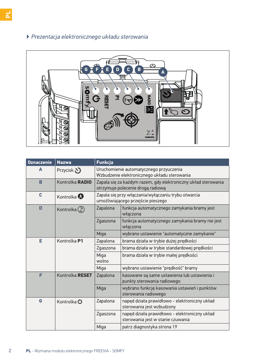
Prezentacja elektronicznego układu sterowania
| Oznaczenie | Nazwa | Funkcja | |
|---|---|---|---|
| A | Przycisk | Uruchomienie automatycznego przyuczenia ; Wzbudzenie elektronicznego układu sterowania | |
| B | Kontrolka RADIO | Zapala się za każdym razem, gdy elektroniczny układ sterowania otrzymuje polecenie drogą radiową | |
| C | Kontrolka | Zapala się przy włączania/wyłączaniu trybu otwarcia umożliwiającego przejście pieszego | |
| D | Kontrolka | Zapalona | funkcja automatycznego zamykania bramy jest włączona |
| Zgaszona | funkcja automatycznego zamykania bramy nie jest włączona | ||
| Miga | wybrano ustawienie "automatyczne zamykanie" | ||
| E | Kontrolka P1 | Zapalona | brama działa w trybie dużej prędkości |
| Zgaszona | brama działa w trybie standardowej prędkości | ||
| Miga wolno | brama działa w trybie małej prędkości | ||
| Miga | wybrano ustawienie "prędkość" bramy | ||
| F | Kontrolka RESET | Zapalona | kasowane są same ustawienia lub ustawienia i punkty sterowania radiowego |
| Miga | wybrano funkcję kasowania ustawień i punktów sterowania radiowego | ||
| G | Kontrolka | Zapalona | napęd działa prawidłowo - elektroniczny układ sterowania jest wzbudzony |
| Zgaszona | napęd działa prawidłowo - elektroniczny układ sterowania jest w stanie czuwania | ||
| Miga | patrz diagnostyka | ||
1 Wymiana modułu elektronicznego
1.1 Montaż nowego modułu elektronicznego
Ze względów bezpieczeństwa czynności te należy wykonywać przy odłączonym zasilaniu.
- Wyłączyć zasilanie instalacji.
- Odkręcić i zdjąć pokrywę napędu.
- Oznaczyć przewód zasilania 230V oraz przewody urządzeń zewnętrznych.
- Zamontować i dokręcić nowy moduł elektroniczny.
- Przypiąć antenę na pokrywie napędu.
Przewody akcesoriów powinny pozostać zaizolowane (np. za pomocą kostek elektrycznych lub taśmy izolacyjnej), dopóki nie zostaną ponownie podłączone, aby uniknąć jakiegokolwiek ryzyka zwarcia.
1.2 Okablowanie napędu
Ze względów bezpieczeństwa czynności te należy wykonywać przy odłączonym zasilaniu. Nie podłączać żadnego przewodu do zacisku M2.
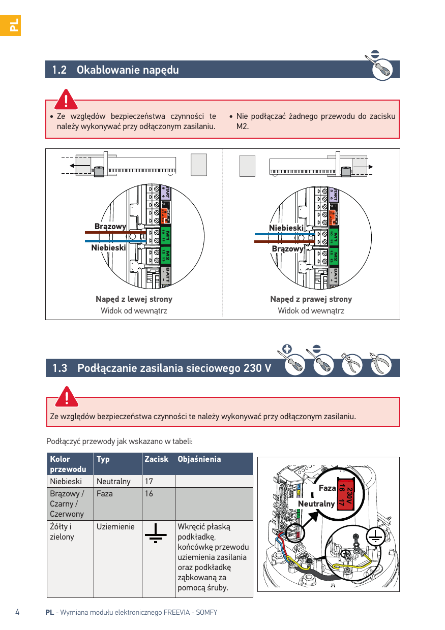
1.3 Podłączanie zasilania sieciowego 230 V
Ze względów bezpieczeństwa czynności te należy wykonywać przy odłączonym zasilaniu.
Podłączyć przewody jak wskazano w tabeli:
| Kolor przewodu | Typ | Zacisk | Objaśnienia |
|---|---|---|---|
| Niebieski | Neutralny | 17 | |
| Brązowy / Czarny / Czerwony | Faza | 16 | |
| Żółty i zielony | Uziemienie | Wkręcić płaską podkładkę, końcówkę przewodu uziemienia zasilania oraz podkładkę ząbkowaną za pomocą śruby. |
1.4 Podłączanie elektronicznego układu sterowania do uziemienia
- Podłączyć dostarczony przewód uziemienia w górnej, prawej części elektronicznego układu sterowania.
- Wkręcić płaską podkładkę, końcówkę przewodu uziemienia oraz podkładkę ząbkowaną za pomocą śruby w górnej części napędu.
1.5 Odblokowanie napędu
Ustawić dźwignię napędu w położeniu. Koło zębate jest zwolnione. Napęd jest odblokowany.
1.6 Zablokowanie napędu
Nigdy nie blokować napędu, gdy brama jest w ruchu, gdyż może to spowodować uszkodzenie zespołu napędowego.
Popchnąć dźwignię napędu w stronę bramy. Napęd jest zablokowany.
2 Uruchomienie i standardowe użytkowanie
2.1 Włączanie zasilania instalacji
- Kontrolka miga (2 razy). Napęd znajduje się pod napięciem i w oczekiwaniu na automatyczne przyuczenie.
- Jeśli kontrolka nie zapala się lub liczba mignięć jest inna niż oczekiwana: patrz diagnostyka.
2.2 Zapisywanie pilota zdalnego sterowania z 2 lub 4 przyciskami
- Położyć pilota zdalnego sterowania, który ma być zaprogramowany na tarczy elektronicznego układu sterowania.
- Wcisnąć krótko przeznaczony do zaprogramowania przycisk pilota zdalnego sterowania. Kontrolka "RADIO" zapala się, po czym gaśnie, gdy przycisk pilota zostaje zwolniony. Tryb całkowitego otwarcia został zaprogramowany w tym przycisku.
2.3 Automatyczne przyuczenie toru przesuwania bramy
Wstępne wymagania - Przed uruchomieniem automatycznego przyuczania należy sprawdzić, czy:
- Instalacja jest pod napięciem: kontrolka miga (2 razy).
- Brama znajduje się w połowie toru przesuwania.
- Napęd jest zablokowany.
Nacisnąć na przycisk elektronicznego układu sterowania.
- Brama otwiera się, zamyka się, otwiera się częściowo i zamyka się ponownie.
- Kontrolka zapala się światłem stałym.
Automatyczne przyuczenie zostało wykonane pomyślnie i napęd działa prawidłowo. Jeśli kontrolka miga (2 razy), należy ponownie wykonać automatyczne przyuczenie. Na koniec procesu automatycznego przyuczenia brama powinna być zamknięta. Jeśli brama jest otwarta, patrz ramka WAŻNE poniżej.
WAŻNE — Jeśli brama jest otwarta na koniec procesu automatycznego przyuczenia:
- Wykasować ustawienia.
- Wyłączyć zasilanie napędu.
- Zamienić przewody podłączone do zacisków 10 i 11 (zielona etykieta M1) elektronicznego układu sterowania (patrz "Okablowanie napędu").
- Odblokować napęd.
- Ustawić bramę w połowie toru przesuwania.
- Zablokować napęd.
- Włączyć zasilanie napędu.
- Ponownie rozpocząć proces automatycznego przyuczenia.
Podczas automatycznego przyuczenia naciśnięcie na przycisk 1 pilota zdalnego sterowania lub na przycisk elektronicznego układu sterowania powoduje zatrzymanie bramy i przyuczania.
2.4 Ustawianie w tryb czuwania / wzbudzenia elektronicznego układu sterowania
W celu sprawdzenia, czy napęd jest zasilany lub w celu sprawdzenia/zmiany ustawień, należy nacisnąć i przytrzymać przez 2 sekundy przycisk, aby wzbudzić elektroniczny układ.
Po wykonaniu automatycznego przyuczenia, elektroniczny układ przechodzi automatycznie w stan czuwania po 5 minutach braku reakcji, aby zaoszczędzić energię. W stanie czuwania, wszystkie kontrolki są zgaszone.
2.5 Montaż pokrywy
- Umieścić pokrywę na napędzie.
- Założyć uszczelkę, aby zapewnić szczelność napędu przy śrubie pokrywy. Dokręcić pokrywę.
3 Okablowanie akcesoriów
Ze względów bezpieczeństwa czynności te należy wykonywać przy odłączonym zasilaniu.
Zaleca się wykonywanie automatycznego przyuczenia toru przesuwania bramy przed podłączeniem akcesoriów (fotokomórki, pomarańczowe światło, itd.)
3.1 Fotokomórki
Okablowanie drugiego zestawu fotokomórek nie jest możliwe do wykonania w przypadku tego zespołu napędowego.
Montaż. Po podłączeniu przewodów do fotokomórek należy: włączyć zasilanie napędu, uruchomić tryb otwierania i zamykania bramy. Fotokomórki są rozpoznawane przez elektroniczny układ sterowania po zakończeniu tego ruchu.
Działanie z wykorzystaniem fotokomórek. Jeżeli fotokomórki zostaną zasłonięte podczas zamykania bramy, brama zatrzyma się i zacznie się ponownie otwierać.
W przypadku usunięcia fotokomórek. Po usunięciu fotokomórek, ponownie włączyć zasilanie napędu, a następnie wykonać procedurę "Wyłączenie trybu automatycznego zamykania - powrót do trybu standardowego działania".
3.2 Pomarańczowe światło
Żarówka MAXIMUM 10 W - 24 V - Użycie żarówki o mocy powyżej 10 W- 24 V może spowodować nieprawidłowe działanie zespołu napędowego.
Działanie pomarańczowego światła. Pomarańczowe światło miga, gdy brama jest w ruchu.
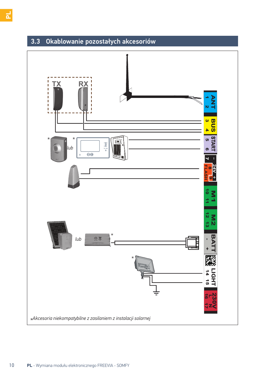
3.3 Okablowanie pozostałych akcesoriów
4 Ustawienia zaawansowane
4.1 Otwarcie umożliwiające przejście pieszego
Działanie trybu otwarcia umożliwiającego przejście pieszego. Naciśnięcie na zaprogramowany przycisk pilota zdalnego sterowania w celu otwarcia umożliwiającego przejście pieszego powoduje otwarcie bramy na około 1 metr. Kolejne naciśnięcie na przycisk powoduje zamknięcie bramy.
Przycisk 1 pilotów zdalnego sterowania z 2 lub 4 przyciskami nie może zostać zaprogramowany do sterowania trybem otwarcia bramy umożliwiającym przejście pieszego.
Włączanie trybu otwarcia umożliwiającego przejście pieszego:
- Wcisnąć i przytrzymać przez 2 s przycisk elektronicznego układu sterowania. Kontrolka zapala się.
- Położyć pilota zdalnego sterowania na tarczy elektronicznego układu sterowania.
- Wcisnąć przycisk 2 pilota zdalnego sterowania. Kontrolki RADIO i zapalają się, po czym gasną. Tryb otwarcia umożliwiającego przejście pieszego zostaje aktywowany w tym przycisku.
Oddalić się od elektronicznego układu sterowania, aby przetestować tryb otwarcia umożliwiającego przejście pieszego.
Wyłączanie trybu otwarcia umożliwiającego przejście pieszego. Powtórzyć procedurę "Włączanie trybu otwarcia umożliwiającego przejście pieszego" za pomocą przycisku, dla którego tryb otwarcia umożliwiającego przejście pieszego powinien być wyłączony. Kontrolka zapala się, a następnie gaśnie. Tryb otwarcia umożliwiającego przejście pieszego zostaje aktywowany w tym przycisku.
4.2 Zamykanie automatyczne
Sposób działania automatycznego zamykania. Wcisnąć przycisk 1 pilota zdalnego sterowania, aby otworzyć bramę. Brama zamyka się po 30 sekundach lub po 5 sekundach w przypadku wykrycia przejścia przez fotokomórki. Automatyczne zamknięcie bramy może zostać przerwane poprzez wciśnięcie przycisku 1 pilota zdalnego sterowania. W celu zamknięcia bramy należy ponownie wcisnąć przycisk 1 pilota zdalnego sterowania.
Funkcja automatycznego zamykania może być włączona tylko jeśli fotokomórki są podłączone i rozpoznane przez elektroniczny układ sterowania napędu.
Włączanie automatycznego zamykania:
- Wcisnąć i przytrzymać przez 2 s przycisk elektronicznego układu sterowania. Kontrolka zapala się.
- Położyć pilota zdalnego sterowania na tarczy elektronicznego układu sterowania.
- Przytrzymać wciśnięty przycisk 1 pilota zdalnego sterowania do momentu, aż kontrolka zacznie migać.
- Przytrzymać wciśnięty przycisk 2 pilota zdalnego sterowania do momentu, aż kontrolka zgaśnie, a następnie zaświeci się światłem stałym.
- Po zwolnieniu przycisku 2, kontrolka miga, należy nacisnąć 3-krotnie na przycisk 1 pilota zdalnego sterowania. Kontrolka pozostaje zapalona. Włączona jest funkcja automatycznego zamykania.
Wyłączenie trybu automatycznego zamykania - powrót do trybu standardowego działania:
- Wcisnąć i przytrzymać przez 2 s przycisk elektronicznego układu sterowania. Kontrolka zapala się.
- Położyć pilota zdalnego sterowania na tarczy elektronicznego układu sterowania.
- Przytrzymać wciśnięty przycisk 1 pilota zdalnego sterowania do momentu, aż kontrolka zacznie migać.
- Wcisnąć przycisk 2 pilota zdalnego sterowania. Kontrolka miga.
- Wcisnąć 3 razy przycisk 1 pilota zdalnego sterowania.
- Kontrolka jest zgaszona. Funkcja automatycznego zamykania jest wyłączona.
4.3 Prędkość przesuwania bramy
Domyślnie brama działa w trybie standardowej prędkości.
NIEBEZPIECZEŃSTWO Jakakolwiek zmiana prędkości bramy powinna być wykonywana przez instalatora specjalizującego się w zakresie urządzeń mechanicznych i automatyki w budynkach mieszkalnych. Wszelkie modyfikacje, które nie są zgodne z powyższymi instrukcjami stanowią zagrożenie dla osób i mienia.
Zakres zastosowania. Ustawić prędkość przesuwania bramy zgodnie z poniższą tabelą:
| Masa bramy | Duża prędkość | Prędkość standardowa | Prędkość wolna |
|---|---|---|---|
| 0 do <100 kg | Tak + listwa czujnikowa* | Tak | Tak |
| 100 do <200 kg | Tak + listwa czujnikowa* | Tak | Tak |
| 200 do <300 kg | Tak + listwa czujnikowa* | Tak + listwa czujnikowa* | Tak |
| 300 do <400 kg | Nie | Tak + listwa czujnikowa* | Tak |
| 400 do <500 kg | Nie | Nie | Tak + listwa czujnikowa* |
| 500 do <600 kg | Nie | Nie | Tak + listwa czujnikowa* |
*Montaż pasywnej listwy czujnikowej (nr kat. 9014597) na bramie jest obowiązkowy.
OSTRZEŻENIE Jeżeli parametr prędkości zostanie zmieniony, instalator musi koniecznie sprawdzić, czy system wykrywania przeszkód jest zgodny z załącznikiem A normy EN 12 453. Nieprzestrzeganie tego zalecenia mogłoby spowodować poważne obrażenia ciała, na przykład przygniecenie przez bramę.
Ustawianie trybu dużej lub małej prędkości:
- Wcisnąć i przytrzymać przez 2 s przycisk elektronicznego układu sterowania. Kontrolka zapala się.
- Położyć pilota zdalnego sterowania na tarczy elektronicznego układu sterowania.
- Przytrzymać wciśnięty przycisk 1 pilota zdalnego sterowania do momentu, aż kontrolka zacznie migać.
- Wcisnąć jeden raz przycisk 1 pilota zdalnego sterowania. Kontrolka P1 miga.
- W celu ustawienia trybu małej prędkości: przytrzymać wciśnięty przycisk 2 do momentu, aż kontrolka P1 zacznie powoli migać (wybrany został tryb małej prędkości). W celu ustawienia trybu dużej prędkości: wcisnąć jeden raz przycisk 2, kontrolka P1 świeci światłem stałym przez 5 sekund po czym zaczyna migać (wybrany został tryb dużej prędkości).
- Wcisnąć 2 razy przycisk 1 pilota zdalnego sterowania. Dla małej prędkości kontrolka P1 miga powoli. Dla dużej prędkości kontrolka P1 pozostaje zapalona.
Powrót do prędkości standardowej:
- Wcisnąć i przytrzymać przez 2 s przycisk elektronicznego układu sterowania. Kontrolka zapala się.
- Położyć pilota zdalnego sterowania na tarczy elektronicznego układu sterowania.
- Przytrzymać wciśnięty przycisk 1 pilota zdalnego sterowania do momentu, aż kontrolka zacznie migać.
- Wcisnąć jeden raz przycisk 1 pilota zdalnego sterowania. Kontrolka P1 miga.
- Wcisnąć jeden raz przycisk 2 pilota zdalnego sterowania. Kontrolka P1 gaśnie na 5 sekund następnie miga.
- Wcisnąć 2 razy przycisk 1 pilota zdalnego sterowania. Kontrolka P1 jest zgaszona. Wybrano tryb prędkości standardowej.
5 Programowanie pilotów zdalnego sterowania
5.1 Dodawanie pilota zdalnego sterowania
- Wcisnąć i przytrzymać przez 2 s przycisk elektronicznego układu sterowania. Kontrolka zapala się.
- Położyć pilota zdalnego sterowania, który ma być zaprogramowany na tarczy elektronicznego układu sterowania.
- Wcisnąć krótko przeznaczony do zaprogramowania przycisk pilota zdalnego sterowania. Kontrolka "RADIO" zapala się, po czym gaśnie, gdy przycisk pilota zostaje zwolniony. Tryb całkowitego otwarcia został zaprogramowany w tym przycisku.
5.2 Kasowanie pilotów zdalnego sterowania
Patrz "Kasowanie ustawień".
6 Usuwanie usterek
Podczas czyszczenia, wykonywania czynności konserwacyjnych i wymiany części, zespół napędowy musi być odłączony od źródła zasilania.
6.1 Pomoc techniczna
Jeśli usterka nadal występuje lub w przypadku innego problemu lub pytań dotyczących zespołu napędowego, prosimy odwiedzić stronę: www.somfy.com
6.2 Wymiana baterii pilota zdalnego sterowania
- Wyjąć zatrzask pilota zdalnego sterowania.
- Włożyć śrubokręt w szczelinę i podnieść pokrywę.
- Wyjąć baterię przy pomocy śrubokręta.
- Wymienić baterię (3 V CR 2430).
6.3 Kasowanie ustawień
W jakim przypadku należy wykasować ustawienia?
- Po automatycznym przyuczeniu, w przypadku zmiany położenia ogranicznika otwarcia, w przypadku zmiany okablowania napędu lub w przypadku dodania listwy czujnikowej na bramie.
- W przypadku ponownego przypadkowego otwarcia bramy w wyniku standardowego użycia bramy.
- Wcisnąć i przytrzymać przez 2 s przycisk elektronicznego układu sterowania. Kontrolka zapala się.
- Umieścić zaprogramowany pilot zdalnego sterowania na tarczy.
- Przytrzymać wciśnięty przycisk 1 pilota zdalnego sterowania do momentu, aż kontrolka zacznie migać.
- Wcisnąć 2 razy przycisk 1 pilota zdalnego sterowania.
- Kontrolka "RESET" miga.
- W celu wykasowania ustawień*: przytrzymać wciśnięty przycisk 2 pilota zdalnego sterowania do momentu, aż kontrolka "RESET" zapali się. W celu wykasowania ustawień* i pilotów zdalnego sterowania/punktów sterowania zapisanych w pamięci: przytrzymać wciśnięty przycisk 2 pilota zdalnego sterowania do momentu, aż wszystkie kontrolki zapalą się.
- Kontrolka miga 2-krotnie (w celu uruchomienia automatycznego przyuczania).
*Tor przesuwania bramy, dezaktywacja ustawień, ...
6.4 Diagnostyka
| Diagnostyka | Przyczyna | Usuwanie usterek |
|---|---|---|
| Napęd nie reaguje na polecenia z pilota zdalnego sterowania | Ograniczony zasięg działania pilota | Sprawdzić baterię pilota. Sprawdzić antenę modułu elektronicznego (przewody, położenie). Sprawdzić, czy żaden element zewnętrzny nie powoduje zakłóceń w przepływie fal radiowych (słup elektryczny, mur zbrojony itd.). W takim przypadku należy przewidzieć antenę niezależną. |
| Niezapisany w pamięci pilot zdalnego sterowania | Zapisać w pamięci pilota. | |
| Napęd odblokowany | Zablokować napęd. | |
| Kontrolka modułu elektronicznego jest zgaszona | Elektroniczny układ sterowania jest w trybie czuwania | Wcisnąć na 2 sekundy, aby wzbudzić elektroniczny układ sterowania. |
| Elektroniczny układ sterowania nie jest zasilany | Sprawdzić zasilanie sieciowe. Sprawdzić przewód zasilający. | |
| 1 mignięcie | Działanie z zasilaniem przez zapasowy akumulator | Sprawdzić zasilanie sieciowe. |
| 2 mignięcia | Napęd w trybie oczekiwania na przyuczenie toru przesuwania bramy | Rozpocząć od nowa procedurę automatycznego przyuczenia. |
| 3 mignięcia | Uszkodzone fotokomórki | Sprawdzić, czy między fotokomórkami nie ma przeszkody. Sprawdzić ustawienie fotokomórek. Sprawdzić przewody fotokomórek. Jeśli fotokomórki zostały celowo odłączone, wykonać procedurę "Wyłączenie trybu automatycznego zamykania - powrót do trybu standardowego działania". |
| 4 mignięcia | Zwarcie w "START" modułu elektronicznego (zaciski 5-6) | Sprawdzić akcesoria podłączone do "START" modułu elektronicznego. |
| 5 mignięć | Włączone zabezpieczenie termiczne napędu | Pozostawić napęd do ostygnięcia przez kilkadziesiąt minut. |
| 6 mignięć | Zwarcie w "BUS" modułu elektronicznego (zaciski 3-4) | Sprawdzić akcesoria podłączone do "BUS" modułu elektronicznego. |
| Zwarcie w "24 V" modułu elektronicznego (zaciski 7-9) | Sprawdzić akcesoria podłączone do "24 V" modułu elektronicznego. | |
| Zwarcie w obrębie "pomarańczowego światła" modułu elektronicznego (zaciski 8-9) | Sprawdzić przewody pomarańczowego światła. | |
| Zwarcie w obrębie napędu | Sprawdzić przewody napędu. | |
| 7 mignięć | Usterka elektroniczna | Skontaktować się z działem pomocy technicznej Somfy. |
7 Dane techniczne
| Zasilanie | 230 V-50 Hz / 24 V (w trybie zasilania energią słoneczną) |
|---|---|
| Typ napędu | 24 V |
| Moc napędu | 120 W |
| Maksymalne zużycie energii (z oświetleniem strefy) | 600 W |
| Zużycie energii w trybie czuwania | 3,5 W |
| Maksymalna, dzienna ilość cykli pracy | 20 cykli / dziennie ; 10 cykli / dziennie w trybie zasilania energią słoneczną |
| Czas otwierania | 16 s w przypadku bramy 150 kg/3m |
| Automatyczne wykrywanie przeszkody | Zgodnie z normą EN 12 453 |
| Temperatura działania | -20°C do +60°C |
| Osłona termiczna | Tak |
| Stopień ochrony | IP 44 |
| Wbudowany odbiornik fal radiowych | Tak |
| Piloty zdalnego sterowania — Częstotliwość radiowa | 433,42 MHz, < 10 mW |
| Piloty zdalnego sterowania — Zasięg użytkowania | ~30 m |
| Piloty zdalnego sterowania — Ilość ustawień pamięci | 16 |
| Wyjście pomarańczowego światła | Miganie, maksymalnie 24 V, 10 W |
| Wyjście oświetlenia | maksymalnie 500 W przy 230 V (wyłącznie halogen lub żarówka) |
| Wyjście zasilania akcesoriów | maks. 24 Vdc / 15 W |
| Wejście zapasowego akumulatora | Tak |
| Wejście fotokomórek | Tak |
| Wejście sterowania typu suchy styk | Tak (nie działa w przypadku zasilania energią słoneczną lub akumulatorem) |
Contacts Somfy
- Somfy France : 0 820 055 055 (0,15€ la minute) — Forum d'entraide : forum.somfy.fr
- Somfy Gmbh : 07472 / 930 - 495 — www.somfy.de
- Somfy Nederland B.V. : 023 56 23 752 — www.somfy.nl
- Somfy Belux NV. : 02 712 07 70 — www.somfy.be
- Somfy Ltd. : (+44) 0113 391 3030 — www.somfy.co.uk
- Somfy Sp. z o.o : 810377199 — www.somfy.pl
- Somfy España SA : 900 20 68 68 — www.somfy.es
- Somfy Portugal : 808100153 — www.somfy.pt
- Somfy Hellas SA : 211 6000 222 — www.somfy.gr
- Somfy Italia SRL : 800827151 — www.somfy.it
- Somfy LLC Russia : 8 (800) 555-60-70 — www.somfy.ru/diy
Somfy SAS, 50 avenue du Nouveau Monde, BP 152 - 74307 Cluses Cedex, France — www.somfy.com