Notice RIB FIT SLIM
Produit concerné
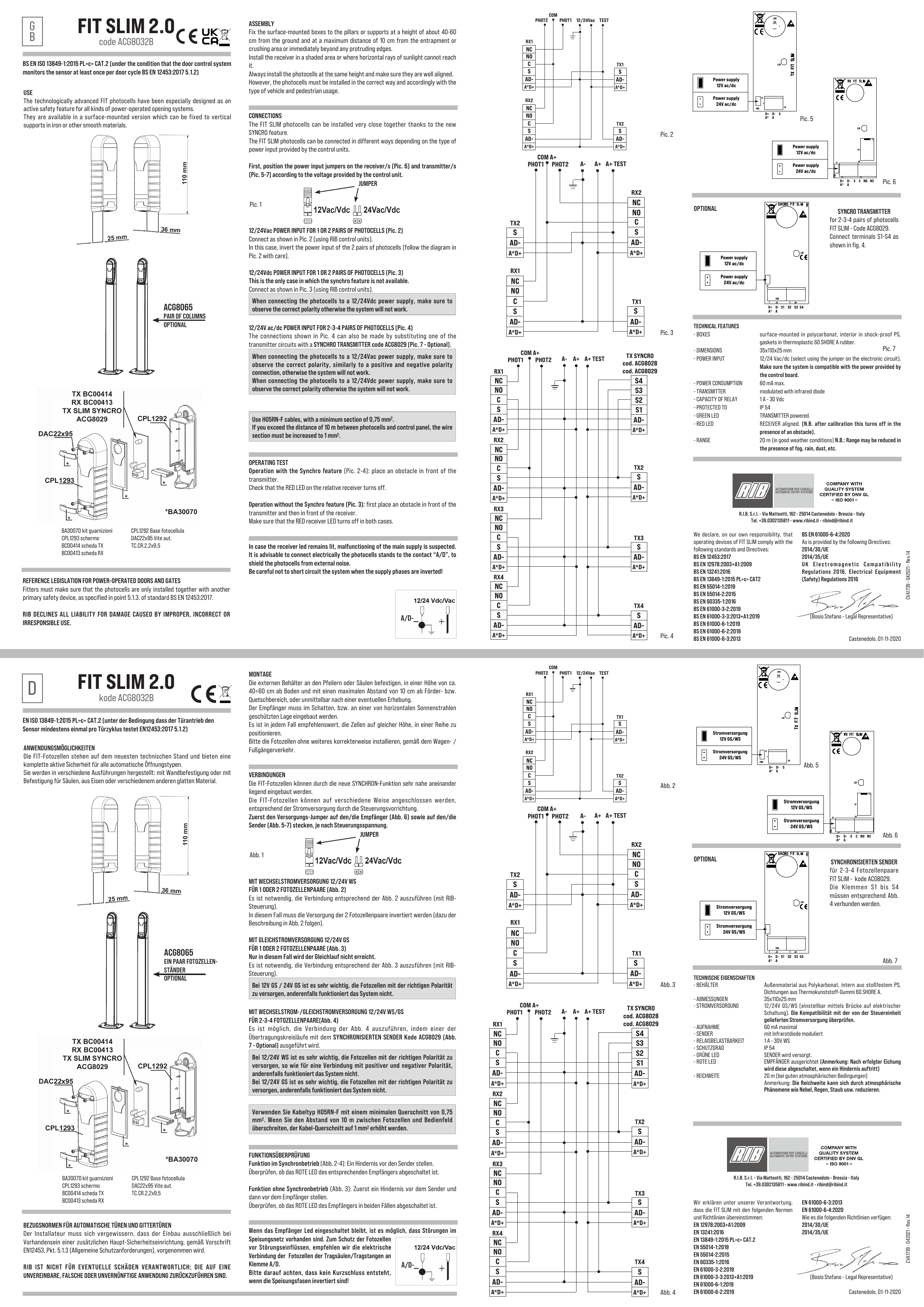
FIT SLIM 2.0 — cod. ACG8032B
Italiano
EN ISO 13849-1:2015 PL»c» CAT.2 (a condizione che il quadro di comando effettui il monitoraggio del rilevatore almeno una volta per ogni ciclo porta EN12453:2017 5.1.2).
Possibilità di impiego
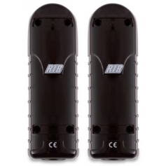
Le fotocellule FIT, tecnologicamente all’avanguardia, soddisfano completamente l’esigenza di una sicurezza attiva su tutti i tipi di aperture automatiche. Sono prodotte nella versione da Parete, da fissare su colonne in ferro o di altro materiale liscio.
Riferimenti normativi per porte e cancelli automatici
L’installatore deve assicurarsi che l’installazione delle fotocellule sia fatta solo in presenza di una ulteriore protezione principale come specificato nella norma EN12453:2017 al punto 5.1.3.
RIB NON PUÓ CONSIDERARSI RESPONSABILE PER EVENTUALI DANNI CAUSATI DA UN USO IMPROPRIO, ERRONEO O IRRAGIONEVOLE.
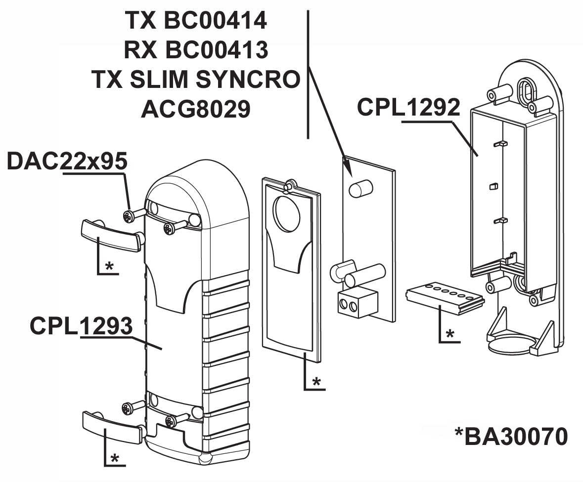
Montaggio
Fissare i contenitori esterni sui pilastri o sulle colonnine ad un’altezza di circa 40÷60 cm dal suolo e ad una distanza max di 10 cm dalla zona di convogliamento o schiacciamento o subito dopo l’ingombro dato da un’eventuale costa.
Installate il ricevitore in ombra o in una posizione in cui il sole non possa battere orizzontalmente. In ogni caso si consiglia di posizionare le fotocellule alla stessa altezza e allineate tra loro.
Installare comunque le fotocellule in modo corretto ed in funzione del tipo di flusso veicolare o pedonale.

Collegamenti
Le fotocellule FIT SLIM possono essere installate vicinissime tra di loro grazie alla nuova funzione di SINCRONISMO.
Le fotocellule FIT SLIM sono collegabili in modo diverso a seconda del tipo di alimentazione fornita dal quadro elettronico di comando.
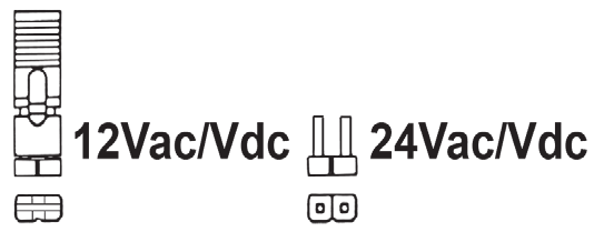
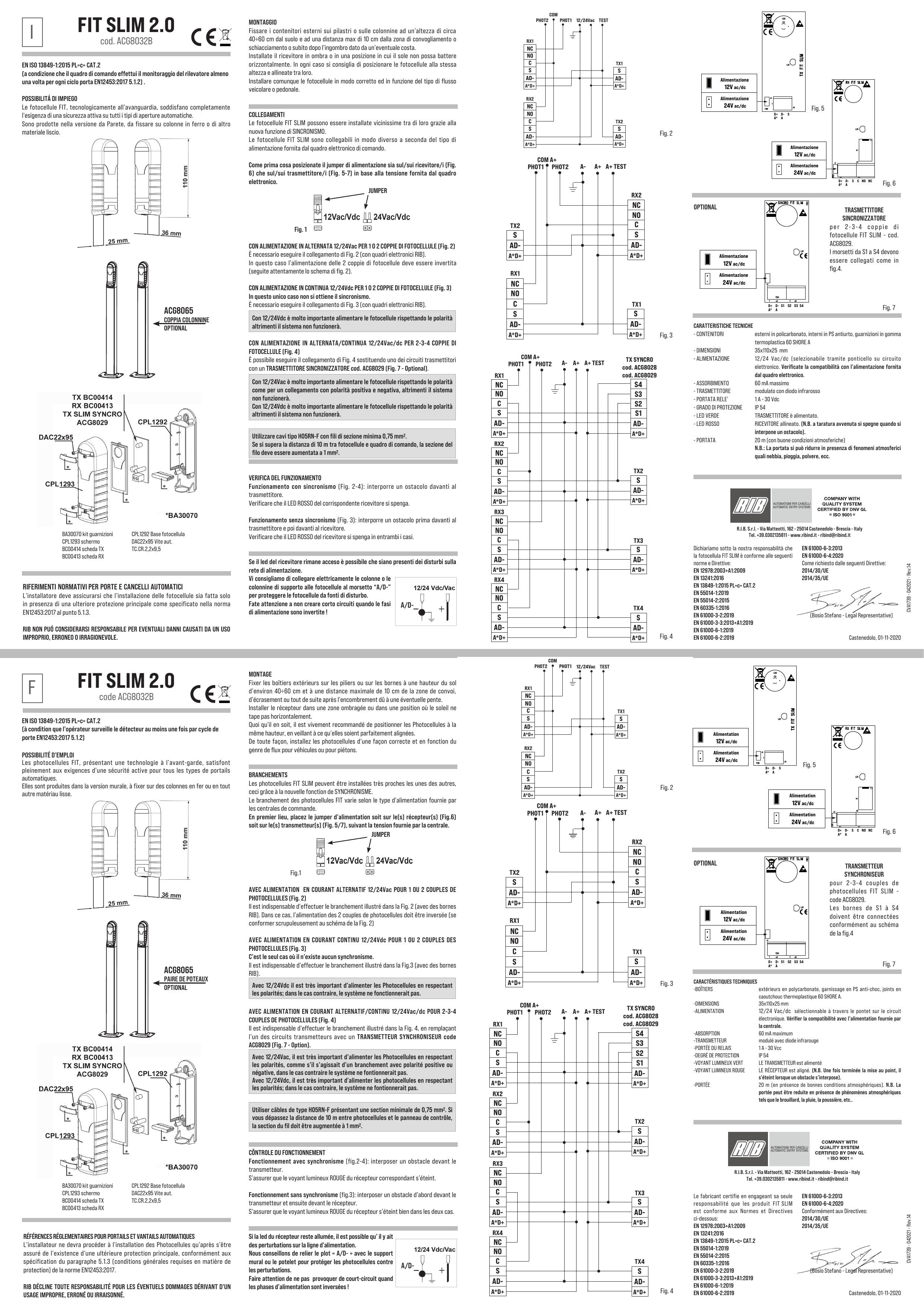
Come prima cosa posizionate il jumper di alimentazione sia sul/sui ricevitore/i (Fig. 6) che sul/sui trasmettitore/i (Fig. 5-7) in base alla tensione fornita dal quadro elettronico (Fig. 1).
Con alimentazione in alternata 12/24Vac per 1 o 2 coppie di fotocellule (Fig. 2)
È necessario eseguire il collegamento di Fig. 2 (con quadri elettronici RIB). In questo caso l’alimentazione delle 2 coppie di fotocellule deve essere invertita (seguite attentamente lo schema di fig. 2).
Con alimentazione in continua 12/24Vdc per 1 o 2 coppie di fotocellule (Fig. 3)
In questo unico caso non si ottiene il sincronismo. È necessario eseguire il collegamento di Fig. 3 (con quadri elettronici RIB). Con 12/24Vdc è molto importante alimentare le fotocellule rispettando le polarità altrimenti il sistema non funzionerà.
Con alimentazione in alternata/continua 12/24Vac/dc per 2-3-4 coppie di fotocellule (Fig. 4)
È possibile eseguire il collegamento di Fig. 4 sostituendo uno dei circuiti trasmettitori con un TRASMETTITORE SINCRONIZZATORE cod. ACG8029 (Fig. 7 - Optional).
Con 12/24Vac è molto importante alimentare le fotocellule rispettando le polarità come per un collegamento con polarità positiva e negativa, altrimenti il sistema non funzionerà. Con 12/24Vdc è molto importante alimentare le fotocellule rispettando le polarità altrimenti il sistema non funzionerà.
Utilizzare cavi tipo H05RN-F con fili di sezione minima 0,75 mm2. Se si supera la distanza di 10 m tra fotocellule e quadro di comando, la sezione del filo deve essere aumentata a 1 mm2.

Verifica del funzionamento
Funzionamento con sincronismo (Fig. 2-4): interporre un ostacolo davanti al trasmettitore. Verificare che il LED ROSSO del corrispondente ricevitore si spenga.
Funzionamento senza sincronismo (Fig. 3): interporre un ostacolo prima davanti al trasmettitore e poi davanti al ricevitore. Verificare che il LED ROSSO del ricevitore si spenga in entrambi i casi.
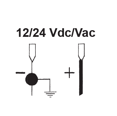
Se il led del ricevitore rimane acceso è possibile che siano presenti dei disturbi sulla rete di alimentazione. Vi consigliamo di collegare elettricamente le colonne o le colonnine di supporto alle fotocellule al morsetto “A/D-” per proteggere le fotocellule da fonti di disturbo.
Fate attenzione a non creare corto circuiti quando le fasi di alimentazione sono invertite!
Trasmettitore sincronizzatore
Per 2-3-4 coppie di fotocellule FIT SLIM - cod. ACG8029. I morsetti da S1 a S4 devono essere collegati come in fig. 4 (Optional).
Caratteristiche tecniche
| Contenitori | Esterni in policarbonato, interni in PS antiurto, guarnizioni in gomma termoplastica 60 SHORE A |
|---|---|
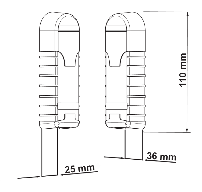
| Dimensioni | 35 × 110 × 25 mm |
| Alimentazione | 12/24 Vac/dc (selezionabile tramite ponticello su circuito elettronico). Verificate la compatibilità con l’alimentazione fornita dal quadro elettronico |
| Assorbimento | 60 mA massimo |
| Trasmettitore | Modulato con diodo infrarosso |
| Portata relè | 1 A - 30 Vdc |
| Grado di protezione | IP 54 |
| Led verde | Trasmettitore è alimentato |
| Led rosso | Ricevitore allineato (a taratura avvenuta si spegne quando si interpone un ostacolo) |
| Portata | 20 m (con buone condizioni atmosferiche). La portata si può ridurre in presenza di fenomeni atmosferici quali nebbia, pioggia, polvere, ecc. |
| Accessorio (optional) | ACG8065 — Coppia colonnine |
Dichiarazione di conformità
Dichiariamo sotto la nostra responsabilità che la fotocellula FIT SLIM è conforme alle seguenti norme e Direttive:
- EN 12978:2003+A1:2009
- EN 13241:2016
- EN 13849-1:2015 PL»c» CAT.2
- EN 55014-1:2019
- EN 55014-2:2015
- EN 60335-1:2016
- EN 61000-3-2:2019
- EN 61000-3-3:2013+A1:2019
- EN 61000-6-1:2019
- EN 61000-6-2:2019
- EN 61000-6-3:2013
- EN 61000-6-4:2020
Come richiesto dalle seguenti Direttive: 2014/30/UE, 2014/35/UE.
Bosio Stefano - Legal Representative — Castenedolo, 01-11-2020
R.I.B. S.r.l. - Via Matteotti, 162 - 25014 Castenedolo - Brescia - Italy — Tel. +39.0302135811 - www.ribind.it - ribind@ribind.it
Français
EN ISO 13849-1:2015 PL»c» CAT.2 (à condition que l’opérateur surveille le détecteur au moins une fois par cycle de porte EN12453:2017 5.1.2).
Possibilité d’emploi
Les photocellules FIT, présentant une technologie à l’avant-garde, satisfont pleinement aux exigences d’une sécurité active pour tous les types de portails automatiques. Elles sont produites dans la version murale, à fixer sur des colonnes en fer ou en tout autre matériau lisse.
Références réglementaires pour portails et vantails automatiques
L’installateur ne devra procéder à l’installation des Photocellules qu’après s’être assuré de l’existence d’une ultérieure protection principale, conformément aux spécifications du paragraphe 5.1.3 (conditions générales requises en matière de protection) de la norme EN12453:2017.
RIB DÉCLINE TOUTE RESPONSABILITÉ POUR LES ÉVENTUELS DOMMAGES DÉRIVANT D’UN USAGE IMPROPRE, ERRONÉ OU IRRAISONNÉ.
Montage
Fixer les boîtiers extérieurs sur les piliers ou sur les bornes à une hauteur du sol d’environ 40÷60 cm et à une distance maximale de 10 cm de la zone de convoi, d’écrasement ou tout de suite après l’encombrement dû à une éventuelle pente.
Installer le récepteur dans une zone ombragée ou dans une position où le soleil ne tape pas horizontalement. Quoi qu’il en soit, il est vivement recommandé de positionner les Photocellules à la même hauteur, en veillant à ce qu’elles soient parfaitement alignées.
De toute façon, installez les photocellules d’une façon correcte et en fonction du genre de flux pour véhicules ou pour piétons.
Branchements
Les photocellules FIT SLIM peuvent être installées très proches les unes des autres, ceci grâce à la nouvelle fonction de SYNCHRONISME.
Le branchement des photocellules FIT varie selon le type d’alimentation fournie par les centrales de commande.
En premier lieu, placez le jumper d’alimentation soit sur le(s) récepteur(s) (Fig. 6) soit sur le(s) transmetteur(s) (Fig. 5/7), suivant la tension fournie par la centrale (Fig. 1).
Avec alimentation en courant alternatif 12/24Vac pour 1 ou 2 couples de photocellules (Fig. 2)
Il est indispensable d’effectuer le branchement illustré dans la Fig. 2 (avec des bornes RIB). Dans ce cas, l’alimentation des 2 couples de photocellules doit être inversée (se conformer scrupuleusement au schéma de la Fig. 2).
Avec alimentation en courant continu 12/24Vdc pour 1 ou 2 couples de photocellules (Fig. 3)
C’est le seul cas où il n’existe aucun synchronisme. Il est indispensable d’effectuer le branchement illustré dans la Fig. 3 (avec des bornes RIB). Avec 12/24Vdc il est très important d’alimenter les Photocellules en respectant les polarités; dans le cas contraire, le système ne fonctionnerait pas.
Avec alimentation en courant alternatif/continu 12/24Vac/dc pour 2-3-4 couples de photocellules (Fig. 4)
Il est indispensable d’effectuer le branchement illustré dans la Fig. 4, en remplaçant l’un des circuits transmetteurs avec un TRANSMETTEUR SYNCHRONISEUR code ACG8029 (Fig. 7 - Option).
Avec 12/24Vac, il est très important d’alimenter les Photocellules en respectant les polarités, comme s’il s’agissait d’un branchement avec polarité positive ou négative, dans le cas contraire le système ne fonctionnerait pas. Avec 12/24Vdc, il est très important d’alimenter les photocellules en respectant les polarités; dans le cas contraire, le système ne fonctionnerait pas.
Utiliser câbles de type H05RN-F présentant une section minimale de 0,75 mm2. Si vous dépassez la distance de 10 m entre photocellules et le panneau de contrôle, la section du fil doit être augmentée à 1 mm2.

Contrôle du fonctionnement
Fonctionnement avec synchronisme (Fig. 2-4) : interposer un obstacle devant le transmetteur. S’assurer que le voyant lumineux ROUGE du récepteur correspondant s’éteint.
Fonctionnement sans synchronisme (Fig. 3) : interposer un obstacle d’abord devant le transmetteur et ensuite devant le récepteur. S’assurer que le voyant lumineux ROUGE du récepteur s’éteint bien dans les deux cas.
Si la led du récepteur reste allumée, il est possible qu’il y ait des perturbations sur la ligne d’alimentation. Nous conseillons de relier le plot « A/D- » avec le support mural ou le potelet pour protéger les photocellules contre les perturbations.
Faire attention de ne pas provoquer de court-circuit quand les phases d’alimentation sont inversées!
Transmetteur synchroniseur
Pour 2-3-4 couples de photocellules FIT SLIM - code ACG8029. Les bornes de S1 à S4 doivent être connectées conformément au schéma de la fig. 4 (Option).
Caractéristiques techniques
| Boîtiers | Extérieurs en polycarbonate, garnissage en PS anti-choc, joints en caoutchouc thermoplastique 60 SHORE A |
|---|---|
| Dimensions | 35 × 110 × 25 mm |
| Alimentation | 12/24 Vac/dc, sélectionnable à travers le pontet sur le circuit électronique. Vérifier la compatibilité avec l’alimentation fournie par la centrale |
| Absorption | 60 mA maximum |
| Transmetteur | Modulé avec diode infrarouge |
| Portée du relais | 1 A - 30 Vcc |
| Degré de protection | IP 54 |
| Voyant lumineux vert | Le transmetteur est alimenté |
| Voyant lumineux rouge | Le récepteur est aligné (une fois terminée la mise au point, il s’éteint lorsqu’un obstacle s’interpose) |
| Portée | 20 m (en présence de bonnes conditions atmosphériques). La portée peut être réduite en présence de phénomènes atmosphériques tels que le brouillard, la pluie, la poussière, etc. |
| Accessoire (option) | ACG8065 — Paire de poteaux |
Déclaration de conformité
Le fabricant certifie en engageant sa seule responsabilité que le produit FIT SLIM est conforme aux Normes et Directives ci-dessous :
- EN 12978:2003+A1:2009
- EN 13241:2016
- EN 13849-1:2015 PL»c» CAT.2
- EN 55014-1:2019
- EN 55014-2:2015
- EN 60335-1:2016
- EN 61000-3-2:2019
- EN 61000-3-3:2013+A1:2019
- EN 61000-6-1:2019
- EN 61000-6-2:2019
- EN 61000-6-3:2013
- EN 61000-6-4:2020
Conformément aux Directives : 2014/30/UE, 2014/35/UE.
Bosio Stefano - Legal Representative — Castenedolo, 01-11-2020
English
BS EN ISO 13849-1:2015 PL»c» CAT.2 (under the condition that the door control system monitors the sensor at least once per door cycle BS EN 12453:2017 5.1.2).
Use
The technologically advanced FIT photocells have been especially designed as an active safety feature for all kinds of power-operated opening systems. They are available in a surface-mounted version which can be fixed to vertical supports in iron or other smooth materials.
Reference legislation for power-operated doors and gates
Fitters must make sure that the photocells are only installed together with another primary safety device, as specified in point 5.1.3 of standard BS EN 12453:2017.
RIB DECLINES ALL LIABILITY FOR DAMAGE CAUSED BY IMPROPER, INCORRECT OR IRRESPONSIBLE USE.
Assembly
Fix the surface-mounted boxes to the pillars or supports at a height of about 40-60 cm from the ground and at a maximum distance of 10 cm from the entrapment or crushing area or immediately beyond any protruding edges.
Install the receiver in a shaded area or where horizontal rays of sunlight cannot reach it. Always install the photocells at the same height and make sure they are well aligned. However, the photocells must be installed in the correct way and accordingly with the type of vehicle and pedestrian usage.
Connections
The FIT SLIM photocells can be installed very close together thanks to the new SYNCRO feature. The FIT SLIM photocells can be connected in different ways depending on the type of power input provided by the control units.
First, position the power input jumpers on the receiver/s (Pic. 6) and transmitter/s (Pic. 5-7) according to the voltage provided by the control unit (Pic. 1).

12/24Vac power input for 1 or 2 pairs of photocells (Pic. 2)
Connect as shown in Pic. 2 (using RIB control units). In this case, invert the power input of the 2 pairs of photocells (follow the diagram in Pic. 2 with care).
12/24Vdc power input for 1 or 2 pairs of photocells (Pic. 3)
This is the only case in which the synchro feature is not available. Connect as shown in Pic. 3 (using RIB control units). When connecting the photocells to a 12/24Vdc power supply, make sure to observe the correct polarity otherwise the system will not work.
12/24V ac/dc power input for 2-3-4 pairs of photocells (Pic. 4)
The connections shown in Pic. 4 can also be made by substituting one of the transmitter circuits with a SYNCHRO TRANSMITTER code ACG8029 (Pic. 7 - Optional). When connecting the photocells to a 12/24Vac power supply, make sure to observe the correct polarity, similarly to a positive and negative polarity connection, otherwise the system will not work. When connecting the photocells to a 12/24Vdc power supply, make sure to observe the correct polarity otherwise the system will not work.
Use H05RN-F cables, with a minimum section of 0,75 mm2. If you exceed the distance of 10 m between photocells and control panel, the wire section must be increased to 1 mm2.
Operating test
Operation with the Synchro feature (Pic. 2-4): place an obstacle in front of the transmitter. Check that the RED LED on the relative receiver turns off.
Operation without the Synchro feature (Pic. 3): first place an obstacle in front of the transmitter and then in front of the receiver. Make sure that the RED receiver LED turns off in both cases.
In case the receiver led remains lit, malfunctioning of the main supply is suspected. It is advisable to connect electrically the photocells stands to the contact “A/D”, to shield the photocells from external noise.
Be careful not to short circuit the system when the supply phases are inverted!
Syncro transmitter
For 2-3-4 pairs of photocells FIT SLIM - Code ACG8029. Connect terminals S1-S4 as shown in fig. 4 (Optional).
Technical features
| Boxes | Surface-mounted in polycarbonate, interior in shock-proof PS, gaskets in thermoplastic 60 SHORE A rubber |
|---|---|
| Dimensions | 35 × 110 × 25 mm |
| Power input | 12/24 Vac/dc (select using the jumper on the electronic circuit). Make sure the system is compatible with the power provided by the control board |
| Power consumption | 60 mA max. |
| Transmitter | Modulated with infrared diode |
| Capacity of relay | 1 A - 30 Vdc |
| Protection | IP 54 |
| Green LED | Transmitter powered |
| Red LED | Receiver aligned (after calibration this turns off in the presence of an obstacle) |
| Range | 20 m (in good weather conditions). Range may be reduced in the presence of fog, rain, dust, etc. |
| Accessory (optional) | ACG8065 — Pair of columns |
Declaration of conformity
We declare, on our own responsibility, that operating devices of FIT SLIM comply with the following standards and Directives:
- BS EN 12453:2017
- BS EN 12978:2003+A1:2009
- BS EN 13241:2016
- BS EN 13849-1:2015 PL»c» CAT2
- BS EN 55014-1:2019
- BS EN 55014-2:2015
- BS EN 60335-1:2016
- BS EN 61000-3-2:2019
- BS EN 61000-3-3:2013+A1:2019
- BS EN 61000-6-1:2019
- BS EN 61000-6-2:2019
- BS EN 61000-6-3:2013
- BS EN 61000-6-4:2020
As is provided by the following Directives: 2014/30/UE, 2014/35/UE, UK Electromagnetic Compatibility Regulations 2016, Electrical Equipment (Safety) Regulations 2016.
Bosio Stefano - Legal Representative — Castenedolo, 01-11-2020
Deutsch
EN ISO 13849-1:2015 PL»c» CAT.2 (unter der Bedingung dass der Türantrieb den Sensor mindestens einmal pro Türzyklus testet EN12453:2017 5.1.2).
Anwendungsmöglichkeiten
Die FIT-Fotozellen stehen auf dem neuesten technischen Stand und bieten eine komplette aktive Sicherheit für alle automatischen Öffnungstypen. Sie werden in verschiedene Ausführungen hergestellt: mit Wandbefestigung oder mit Befestigung für Säulen, aus Eisen oder verschiedenem anderen glatten Material.
Bezugsnormen für automatische Türen und Gittertüren
Der Installateur muss sich vergewissern, dass der Einbau ausschließlich bei Vorhandensein einer zusätzlichen Haupt-Sicherheitseinrichtung, gemäß Vorschrift EN12453, Pkt. 5.1.3 (Allgemeine Schutzanforderungen), vorgenommen wird.
RIB IST NICHT FÜR EVENTUELLE SCHÄDEN VERANTWORTLICH, DIE AUF EINE UNVEREINBARE, FALSCHE ODER UNVERNÜNFTIGE ANWENDUNG ZURÜCKZUFÜHREN SIND.
Montage
Die externen Behälter an den Pfeilern oder Säulen befestigen, in einer Höhe von ca. 40÷60 cm ab Boden und mit einem maximalen Abstand von 10 cm ab Förder- bzw. Quetschbereich, oder unmittelbar nach einer eventuellen Erhebung.
Der Empfänger muss im Schatten, bzw. an einer von horizontalen Sonnenstrahlen geschützten Lage eingebaut werden. Es ist in jedem Fall empfehlenswert, die Zellen auf gleicher Höhe, in einer Reihe zu positionieren. Bitte die Fotozellen ohne weiteres korrekterweise installieren, gemäß dem Wagen- / Fußgängerverkehr.
Verbindungen
Die FIT-Fotozellen können durch die neue SYNCHRON-Funktion sehr nahe aneinander liegend eingebaut werden. Die FIT-Fotozellen können auf verschiedene Weise angeschlossen werden, entsprechend der Stromversorgung durch die Steuerungsvorrichtung.
Zuerst den Versorgungs-Jumper auf den/die Empfänger (Abb. 6) sowie auf den/die Sender (Abb. 5-7) stecken, je nach Steuerungsspannung (Abb. 1).
Mit Wechselstromversorgung 12/24V WS für 1 oder 2 Fotozellenpaare (Abb. 2)
Es ist notwendig, die Verbindung entsprechend der Abb. 2 auszuführen (mit RIB-Steuerung). In diesem Fall muss die Versorgung der 2 Fotozellenpaare invertiert werden (dazu der Beschreibung in Abb. 2 folgen).
Mit Gleichstromversorgung 12/24V GS für 1 oder 2 Fotozellenpaare (Abb. 3)
Nur in diesem Fall wird der Gleichlauf nicht erreicht. Es ist notwendig, die Verbindung entsprechend der Abb. 3 auszuführen (mit RIB-Steuerung). Bei 12V GS / 24V GS ist es sehr wichtig, die Fotozellen mit der richtigen Polarität zu versorgen, anderenfalls funktioniert das System nicht.
Mit Wechselstrom-/Gleichstromversorgung 12/24V WS/GS für 2-3-4 Fotozellenpaare (Abb. 4)
Es ist möglich, die Verbindung der Abb. 4 auszuführen, indem einer der Übertragungskreisläufe mit dem SYNCHRONISIERTEN SENDER Kode ACG8029 (Abb. 7 - Optional) ausgeführt wird. Bei 12/24V WS ist es sehr wichtig, die Fotozellen mit der richtigen Polarität zu versorgen, so wie für eine Verbindung mit positiver und negativer Polarität, anderenfalls funktioniert das System nicht. Bei 12/24V GS ist es sehr wichtig, die Fotozellen mit der richtigen Polarität zu versorgen, anderenfalls funktioniert das System nicht.
Verwenden Sie Kabeltyp H05RN-F mit einem minimalen Querschnitt von 0,75 mm2. Wenn Sie den Abstand von 10 m zwischen Fotozellen und Bedienfeld überschreiten, der Kabel-Querschnitt auf 1 mm2 erhöht werden.
Funktionsüberprüfung
Funktion im Synchronbetrieb (Abb. 2-4): Ein Hindernis vor den Sender stellen. Überprüfen, ob das ROTE LED des entsprechenden Empfängers abgeschaltet ist.
Funktion ohne Synchronbetrieb (Abb. 3): Zuerst ein Hindernis vor dem Sender und dann vor dem Empfänger stellen. Überprüfen, ob das ROTE LED des Empfängers in beiden Fällen abgeschaltet ist.
Wenn das Empfänger-Led eingeschaltet bleibt, ist es möglich, dass Störungen im Speisungsnetz vorhanden sind. Zum Schutz der Fotozellen vor Störungseinflüssen, empfehlen wir die elektrische Verbindung der Fotozellen der Tragsäulen/Tragstangen an Klemme A/D.
Bitte darauf achten, dass kein Kurzschluss entsteht, wenn die Speisungsfasen invertiert sind!
Synchronisierter Sender
Für 2-3-4 Fotozellenpaare FIT SLIM - kode ACG8029. Die Klemmen S1 bis S4 müssen entsprechend Abb. 4 verbunden werden (Optional).
Technische Eigenschaften
| Behälter | Außenmaterial aus Polykarbonat, intern aus stoßfestem PS, Dichtungen aus Thermokunststoff-Gummi 60 SHORE A |
|---|---|
| Abmessungen | 35 × 110 × 25 mm |
| Stromversorgung | 12/24V GS/WS (einstellbar mittels Brücke auf elektrischer Schaltung). Die Kompatibilität mit der von der Steuereinheit gelieferten Stromversorgung überprüfen |
| Aufnahme | 60 mA maximal |
| Sender | Mit Infrarotdiode moduliert |
| Relaisbelastbarkeit | 1 A - 30V WS |
| Schutzgrad | IP 54 |
| Grüne LED | Sender wird versorgt |
| Rote LED | Empfänger ausgerichtet (nach erfolgter Eichung wird diese abgeschaltet, wenn ein Hindernis auftritt) |
| Reichweite | 20 m (bei guten atmosphärischen Bedingungen). Die Reichweite kann sich durch atmosphärische Phänomene wie Nebel, Regen, Staub usw. reduzieren |
| Zubehör (optional) | ACG8065 — Ein Paar Fotozellenständer |
Konformitätserklärung
Wir erklären unter unserer Verantwortung, dass die FIT SLIM mit den folgenden Normen und Richtlinien übereinstimmen:
- EN 12978:2003+A1:2009
- EN 13241:2016
- EN 13849-1:2015 PL»c» CAT.2
- EN 55014-1:2019
- EN 55014-2:2015
- EN 60335-1:2016
- EN 61000-3-2:2019
- EN 61000-3-3:2013+A1:2019
- EN 61000-6-1:2019
- EN 61000-6-2:2019
- EN 61000-6-3:2013
- EN 61000-6-4:2020
Wie es die folgenden Richtlinien verfügen: 2014/30/UE, 2014/35/UE.
Bosio Stefano - Legal Representative — Castenedolo, 01-11-2020
R.I.B. S.r.l. - Via Matteotti, 162 - 25014 Castenedolo - Brescia - Italy — Tel. +39.0302135811 - www.ribind.it - ribind@ribind.it