Notice CARDIN CDR999
Produit concerné
Descrizione
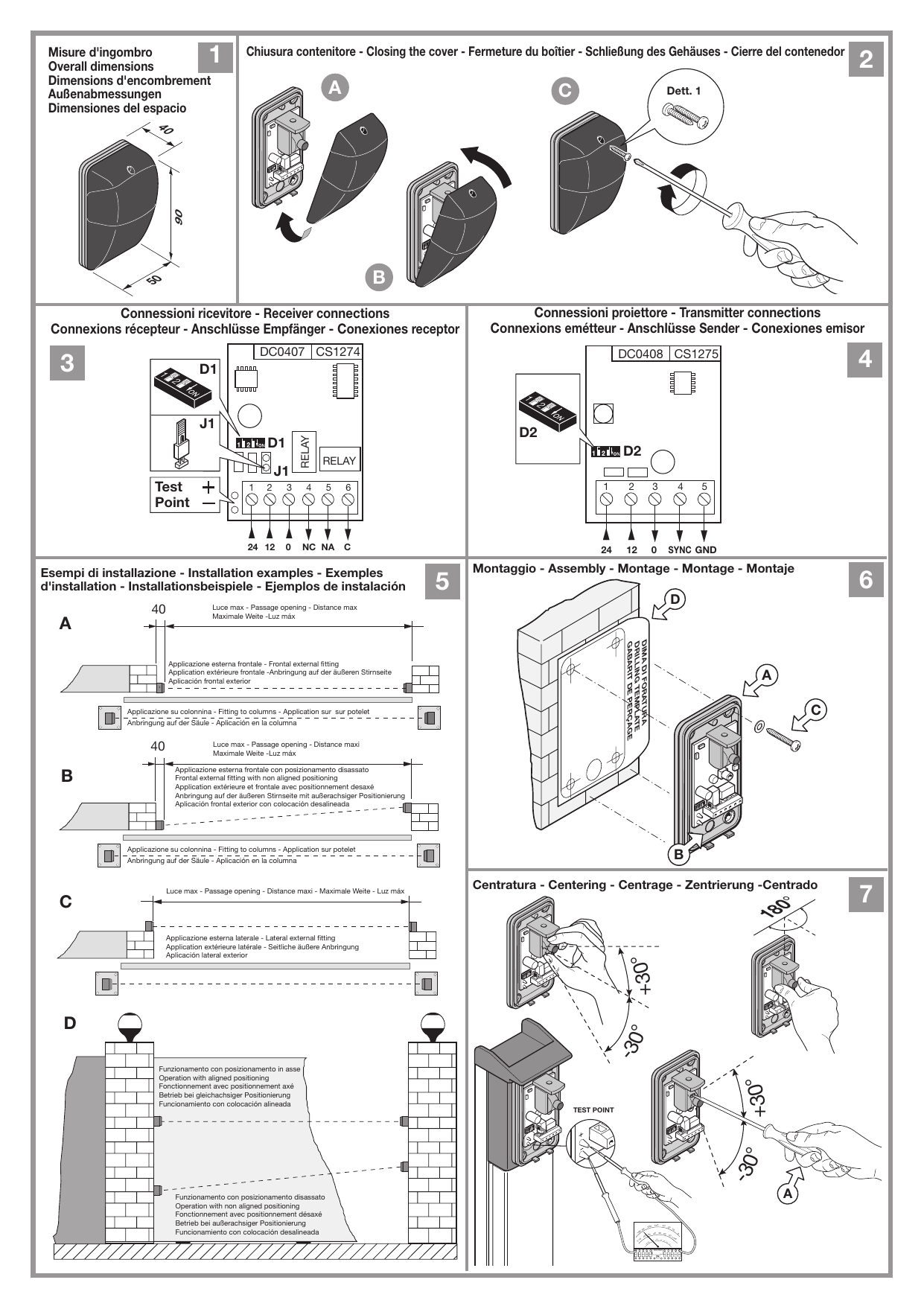
Barriera all'infrarosso modulato composta da proiettore e ricevitore. Le apparecchiature sono alloggiate in un contenitore plastico antiurto a tenuta d'acqua con predisposizione per tutti i sistemi di fissaggio. L'ottica è regolabile su snodi frizionati e autobloccanti sia orizzontalmente, potendo compiere una rotazione di 180°, che verticalmente con una rotazione possibile di ± 30° rispetto alla posizione standard.
Apparecchiatura a doppio relé con scambi in serie, il contatto NC è conforme alle norme della categoria 3 della UNI EN ISO 13849-1 (aggiornamento della EN954-1). Possibilità di collegare un massimo di 3 coppie di fotocellule sincronizzando la trasmissione (sistema multiplexato).
Possibilità d'impiego
La barriera a raggio infrarosso rappresenta un efficiente sistema di sicurezza per la protezione di passaggi o spazi soggetti ad installazioni automatizzate di porte e cancelli controllati a distanza. L'uso e l'installazione di queste apparecchiature deve rispettare rigorosamente le indicazioni fornite dal costruttore e le norme di sicurezza vigenti.
Versioni
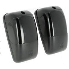
CDR999 La confezione comprende gli elementi per l'applicazione in superficie: 1 proiettore; 1 ricevitore; serie di viterie e guarnizioni.
Caratteristiche tecniche
| Emissione infrarossa | diodo GaAs (Arseniuro di Gallio), portante a 25 kHz e modulante a 70 Hz |
|---|---|
| Lunghezza d'onda | 950 nm |
| Alimentazione | 12 - 24 Vac/dc |
| Relé max potenza commutabile (carico resistivo) | 28W in dc / 60VA in ac; tensione max 30 Vac/dc; corrente max 500 mA |
| Tempo di intervento | 30 ms (singola fotocellula); 100 ms (sistema multiplexato) |
| Assorbimenti | 12 Vac/dc: 51 mA ricevitore + 31 mA proiettore; 24 Vac/dc: 53 mA ricevitore + 33 mA proiettore |
| Temperatura di funzionamento | -10…+55 °C |
| Grado di protezione | IP55 |
| Portata | 10 m in tutte le condizioni, anche con fitta nebbia, pioggia o polvere |
Proiettore (fig. 4)
- led verde di segnalazione di rete;
- DIP-SWITCH "D2" per configurazione sistema multiplexato.
Ricevitore (fig. 3)
Attenzione: La fotocellula esegue un autotest interno ogni minuto, pertanto è normale che, con sistema a riposo, il LED rosso si accenda per un istante ogni minuto.
- led rosso acceso fisso: fotocellula non allineata o raggio interrotto;
- led rosso lampeggiante ogni secondo: fotocellula guasta;
- test point (per centratura fine);
- DIP-SWITCH "D1" per configurazione sistema multiplexato;
- jumper "J1" per selezionare modalità contatto di uscita (contatto puro o con resistenza 8,2 kΩ).
Installazione
Nota: In caso di installazioni comprendenti più apparecchiature è consigliabile realizzare una connessione a sistema multiplexato in modo da evitare interferenze fra le coppie di fotocellule. In tal caso, un proiettore è associato al suo ricevitore impostando DIP 1, 2 in modo identico su entrambi.
Installazione a superficie
L'installazione è possibile su ogni tipo di struttura, consentendo oltre al posizionamento standard il posizionamento laterale (portando così le apparecchiature fuori della luce del passaggio) e il posizionamento proiettore/ricevitore a quote differenziate (per superare problemi su strutture particolari), (part. a-b-c-d, fig. 5).
Nota: nelle installazioni dove il raggio infrarosso passa attraverso le zone maggiormente curvate del vetrino la portata massima potrebbe risultare ridotta.
Attenzione! Non staccare mai la scheda elettronica dalla base di supporto; usare solo le viterie in dotazione al prodotto.
- per l'apertura e chiusura dei contenitori vedere figura 2;
- stabilire i punti di fissaggio a superficie in base alla necessità d'impianto;
- prevedere il percorso cavi sulla struttura fino ai punti di fissaggio;
- servendosi della dima di foratura fornita nell'imballo, tracciare i fori di fissaggio ("D" fig. 6);
- fissare la base con l'apposita guarnizione a parete ("A" fig. 6), utilizzando unicamente le viti con rondella fornite nella confezione, passando i cavi di collegamento sull'apposito foro "B";
- eseguire le connessioni elettriche (fig. 3, 4);
- eseguire, manovrando sull'ottica, il corretto allineamento tra proiettore e ricevitore e verificare che la frizione dell'ottica sia ben serrata (fig. 7);
- per una regolazione fine (su/giù) è possibile utilizzare un attrezzo appuntito da inserire nella fessura superiore dell'ottica (vedi "A" fig. 7);
- per la chiusura del vetrino utilizzare solo ed esclusivamente le due viti che si trovano nello scomparto superiore della confezione di viterie (vedi dett. "1" fig. 2).
Connessioni e impostazioni
- eseguire le connessioni secondo lo schema (fig. 3, 4);
- impostare il jumper "J1" del ricevitore secondo la modalità contatto di uscita:
- jumper inserito: uscita contatto puro (C-NA-NC);
- jumper disinserito: uscita 8,2 kΩ (a riposo: 8,2 kΩ tra i morsetti 4 e 6).
- impostare tutti i DIP-SWITCH a OFF sia sul ricevitore sia sul proiettore;
- alimentati proiettore e ricevitore risulterà: sul proiettore led verde acceso permanentemente e sul ricevitore led rosso acceso con fotocellula non centrata o spento con fotocellula centrata;
- sezione minima dei cavi di connessione: 0.2 mm² (AWG #24).
Eseguire la centratura nel modo seguente
- inserire i puntali di un tester analogico (2 Vdc fondoscala) nelle apposite zone di prova (test point) rispettando l'esatta polarità, come da contrassegni sulla scheda (fig. 7);
- centrare le ottiche in modo da ottenere sul tester la lettura massima considerando come riferimento i valori riportati in tabella;
- i valori riportati in tabella sono puramente indicativi e dipendono dalle condizioni atmosferiche.
| Distanza (m) | Tensione test point (V) |
|---|---|
| 3 | 1,6 |
| 5 | 1,2 |
| 8 | 0,7 |
| 10 | 0,4 |
Sistema multiplexato (max 3 coppie)
- posizionare tutti i proiettori sullo stesso lato;
- sui proiettori collegare in parallelo tutti gli ingressi SYNC e collegare in parallelo tutti gli ingressi GND;
- alimentare e centrare le coppie di fotocellule una alla volta seguendo tutti i passi del paragrafo "connessioni e centratura";
- eseguita separatamente la centratura di tutte le coppie di fotocellule, impostare su ciascuna coppia i DIP da 1 a 2 (proiettore e ricevitore) progressivamente secondo le configurazioni della tabella, partendo dalla prima che individua la coppia "master";
- alimentare tutte le coppie di fotocellule: il sistema multiplexato è configurato.
| Coppia | dip 1 | dip 2 |
|---|---|---|
| 1 | ON | OFF |
| 2 | OFF | ON |
| 3 | ON | ON |
Modulated infrared barrier (EN)
Description
Modulated infrared barrier consisting of a transmitter and a receiver. The equipment is housed in a shockproof and waterproof plastic casing. The adjustable lens, set on a self lubricating and self locking ball joint, can be adjusted through 180° horizontally and plus or minus 30° vertically. The equipment has a double relay with serial exchange. The NC contact conforms to category 3 of the directive UNI EN ISO 13849-1 (update of the EN954-1). It is possible to connect up to 3 pairs of photocells and synchronize the transmission (multiplex system).
Use
The infrared barrier constitutes an efficient safety system for the protection of passageways or spaces which are equipped with automatic door or gate systems. The use and installation of these devices must respect the safety standards and regulations in force.
Versions
CDR999 The package contains the components required for surface installations: 1 transmitter; 1 receiver; set of screws and gaskets.
Technical specifications
| Infrared emission | double emitter GaAs (Galium Arsenide) diode, range 25 kHz, continuous modulation at 70 Hz |
|---|---|
| Infrared emission wavelength | 950 nm |
| Power supply | 12 - 24 Vac/dc |
| Max commutable relay power (resistive load) | 28W in dc / 60VA in ac; max voltage 30 Vac/dc; max current 500 mA |
| Intervention time | 30 ms (single photoelectric cells); 100 ms (multiplex system) |
| Power consumption | 12 Vac/dc: 51 mA receiver + 31 mA transmitter; 24 Vac/dc: 53 mA receiver + 33 mA transmitter |
| Operating temperature | -10…+55 °C |
| Protection grade | IP55 |
| Range | 10 m under all weather conditions such as thick fog, rain and dust |
Transmitter (fig. 4)
- Green power on led;
- Dip-switch "D2" multiplex installation settings.
Receiver (fig. 3)
Attention: The photoelectric cell carries out an internal auto test every minute, it is therefore normal that when the system is at rest, the red LED will light for an instant every minute.
- Red led lit continuously: photocell disturbed or misaligned;
- Red led lit flashing each second: photocell not functioning;
- Test point for fine tuning;
- Dip-switch "D1" multiplex installation settings and relay delay mode;
- Jumper "J1" for selecting the output mode (potential free or resistive contact 8,2 kΩ).
Installation
Note: In cases where the installation consists of more than one device you are advised to use the multiplex function so as to avoid interference between the beams. In this case each transmitter is associated with its receiver by setting dips 1 and 2 identically on both.
Surface mounted installation
Installation is possible on all types of structure. Other than the standard aligned positioning the device can also be positioned both laterally (moving the device out of the passageway) and at different heights in order to solve problems posed by different structures (detail a-b-c-d, fig. 5).
Note: in installations where the infrared beam passes through the highly curved parts of the cover the maximum range of the devices could be reduced.
Attention! The electronic card must never be removed from its support base. Only use the screws supplied with the devices.
- to open and close the container carefully follow the sequence shown in fig. 2;
- choose the points at which the devices are to be surface mounted, according to the requirements of the system;
- work out the run of the cables from the structure to the point of connection;
- using the template supplied with the package trace the positioning holes ("D" fig. 6);
- fasten the base and relative sealing gasket to the wall ("A" fig. 6), making sure that you use the washer supplied with the package, and pass the wiring through the hole "B";
- carry out the electrical connection (fig. 3, 4);
- align the projector and the receiver by rotating the optic and check that the optic lock nut is well tightened (fig. 7);
- replace the infrared cover by placing it against the lower seal and rotating it until you hear the click meaning the holding teeth have locked the cover (see "A" fig. 2);
- when fine tuning the beam (upwards and downwards) it is possible to insert a pointed tool into the upper slot on the optic (see "A" fig. 7);
- to close the infrared cover only use the two screws that are housed, separately in the upper compartment of the bag of screws (see detail "1" fig. 2).
Connections and setting
- carry out the electrical connection as shown in the drawings (fig. 3, 4);
- set jumper "J1" according to the type of relay output:
- jumper inserted: potential free contact (C-NO-NC);
- jumper not inserted: 8,2 kΩ output (8,2 kΩ between binding posts 4 and 6 at rest)
- set all the dip switches to "OFF" both on the receiver and the transmitter;
- power up the receiver and transmitter: the green LED on the transmitter should remain lit constantly and the red LED on the receiver should be lit if the photoelectric cells are not aligned and OFF if they are aligned;
- the minimum allowed cable cross section is: 0.2 mm² (AWG #24).
Connections and centring
- insert the probes of a normal tester (lowest setting 2 Vdc) into the test point maintaining the correct polarity as indicated on the p.c.b card;
- centre the lenses so you obtain a maximum reading on the tester referring to the distance/test point table;
- the values shown in the table are indicative parameters and depend on the atmospheric conditions.
| Distance (m) | Test point value |
|---|---|
| 3 | 1,6 |
| 5 | 1,2 |
| 8 | 0,7 |
| 10 | 0,4 |
Multiplex system (max. three pairs)
- position all the transmitters on the same side;
- connect all the SYNC inputs on the receivers in parallel and connect the GND inputs in parallel;
- power up the pairs of photoelectric cells and centre them by following the paragraph "Connections and centring";
- carry out the centring procedure separately for each pair of photoelectric cells. Set dips 1 and 2 on each pair (transmitter and receiver) progressively according to the configuration in the table, starting with the master pair;
- power up all the pairs of photoelectric cells and you have finished setting the multiplex installation.
| Pair | dip 1 | dip 2 |
|---|---|---|
| 1 | ON | OFF |
| 2 | OFF | ON |
| 3 | ON | ON |
Barrière à l'infrarouge modulé (FR)
Descriptif
Barrage à l'infrarouge modulé, constitué d'un émetteur et d'un récepteur logés sous boîtiers plastiques antichoc et étanches, prédisposés pour tous les systèmes de fixation. La tête optique, montée sur pivot orientable et autobloquant, est réglable horizontalement par rotation de 180°, et verticalement par rotation de ± 30° par rapport à la position standard. Appareil à double relais avec contact inverseur en série. Le contact N.F. est conforme aux normes de la catégorie 3 de la UNI EN ISO 13849-1 (mise à jour de la EN954-1). Possibilité de raccorder un maximum de 3 couples de cellules photoélectriques par synchronisation de l'émission (système multiplexé).
Domaine d'application
Le barrage à rayon infrarouge est destiné à assurer efficacement la sécurité des personnes et des biens lors de l'actionnement de portes et portails commandés à distance. Pour l'utilisation et la pose de ces appareils, se conformer rigoureusement aux instructions fournies par le Fabricant et aux normes de sécurité en vigueur.
Versions
CDR999 La boîte contient les éléments nécessaires à une application en saillie : 1 émetteur; 1 récepteur et un jeu de vis et de joints.
Caractéristiques techniques
| Émission infrarouge | diode GaAs (arséniure de gallium), porteuse à 25 kHz et modulation à 70 Hz |
|---|---|
| Longueur d'onde | 950 nm |
| Alimentation | 12 - 24 Vac/dc |
| Consommation max. de commutation du relais (charge résistive) | 28W en dc / 60VA en ac; tension maxi 30 Vac/dc; courant maxi 500 mA |
| Temps d'intervention | 30 ms (une seule cellule); 100 ms (système multiplexé) |
| Intensité absorbée | 12 Vac/dc: 51 mA récepteur + 31 mA émetteur; 24 Vac/dc: 53 mA récepteur + 33 mA émetteur |
| Température de fonctionnement | -10…+55 °C |
| Indice de protection | IP55 |
| Portée | 10 m quelles que soient les conditions climatiques (brouillard épais, pluie ou poussière) |
Émetteur (fig. 4)
- Led verte de signalisation de mise sous tension.
- DIP-SWITCH "D2" pour configuration du système multiplexé.
Récepteur (fig. 3)
Attention : vu que la cellule photoélectrique lance un autotest interne toutes les minutes, il est normal que, avec système en veille, la LED rouge de chaque cellule photoélectrique s'allume un instant chaque minute.
- Led rouge allumée fixe : cellule photoélectrique désalignée ou occultée.
- Led rouge clignotante toutes les secondes : cellule photoélectrique défectueuse.
- Test point (pour centrage de précision).
- DIP-SWITCH "D1" pour la configuration du système multiplexé.
- Cavalier "J1" pour la sélection du mode de fonctionnement contact de sortie (contact non alimenté ou avec résistance 8,2 kΩ).
Pose
Nota : en cas d'installation comprenant plusieurs appareils, il est conseillé de mettre en place un système multiplexé, afin de parer aux risques d'interférence entre les différents couples de cellules photoélectriques. Dans ce cas, un projecteur est associé à son récepteur en configurant les DIPS 1 et 2 de la même façon sur les deux.
Montage en saillie
Applicables sur n'importe quelle structure, ces appareils peuvent être montés aussi bien en position standard qu'en position latérale (ce qui permet de les déporter par rapport au passage) et à des hauteurs différentes l'un par rapport à l'autre (pour solutionner les problèmes sur structures particulières) (détails a-b-c-d, fig. 5).
Nota : dans les installations où le rayon infrarouge passe à travers les zones plus bombées du verre, la portée maximale pourrait être réduite.
Attention ! Ne jamais détacher la carte électronique de son support; utiliser exclusivement les vis fournies en dotation avec le produit.
- pour l'ouverture et la fermeture des boîtiers, voir figure 2;
- déterminer les points de fixation en saillie en fonction de la particularité de l'installation;
- prévoir le chemin des câbles sur la structure jusqu'aux points de fixation;
- tracer les trous de fixation ("D" fig. 6) à l'aide du gabarit de perçage qui se trouve dans la boîte;
- fixer l'embase avec le joint relatif au mur ("A" fig. 6) après avoir passé les câbles de branchement à travers le trou "B" prévu à cet effet. Pour la fixation, utiliser exclusivement les vis et les rondelles qui se trouvent dans la boîte;
- effectuer les branchements électriques (fig. 3 et 4);
- aligner correctement l'émetteur par rapport au récepteur en intervenant sur la tête optique, et s'assurer du bon serrage de l'articulation de la tête optique (fig. 7);
- pour un réglage de précision (vers le bas/haut), il est possible d'utiliser un outil pointu à introduire dans la fente située en partie haute de la tête optique (voir "A" fig. 7);
- pour la fixation du verre, utiliser exclusivement les deux vis qui se trouvent dans la division supérieure du sachet à vis (voir détail "1" fig. 2).
Connexions et configurations
- effectuer les connexions suivant le schéma (fig. 3, 4);
- configurer le cavalier "J1" selon le mode de fonctionnement du contact de sortie :
- cavalier connecté : sortie contact non alimenté (C-NO-NF),
- cavalier déconnecté : sortie 8,2 kΩ (en veille : 8,2 kΩ entre les bornes 4 et 6)
- placer sur OFF tous les DIP-SWITCHES qui se trouvent sur l'émetteur et sur le récepteur;
- une fois que l'émetteur et le récepteur sont sous tension, la led verte sur l'émetteur est allumée en permanence et, sur le récepteur, si la led rouge est allumée, les cellules photoélectriques ne sont pas alignées, et si la led est éteinte, elles sont alignées;
- la section minimum des câbles de branchement est de 0,2 mm² (AWG #24).
Effectuer le centrage de la façon suivante
- introduire les pointes d'un testeur analogique (2 Vdc échelle maximum) aux endroits de contrôle (test point) en respectant la polarité marquée sur la carte (fig. 7);
- orienter la tête optique de manière à lire sur le testeur la valeur maximale en prenant comme référence les valeurs indiquées au tableau;
- les valeurs indiquées au tableau, fournies à titre purement indicatif, sont liées aux conditions climatiques du lieu d'implantation.
| Distance (m) | Valeur Test point |
|---|---|
| 3 | 1,6 |
| 5 | 1,2 |
| 8 | 0,7 |
| 10 | 0,4 |
Système multiplexé (max 3 couples)
- placer tous les émetteurs du même côté;
- sur les émetteurs, brancher en parallèle toutes les entrées SYNC et brancher en parallèle toutes les entrées GND;
- mettre sous tension et aligner les couples de cellules photoélectriques l'un après l'autre en observant toutes les étapes du paragraphe "Connexions et centrage";
- une fois que le centrage de tous les couples a été effectué l'un après l'autre, configurer sur chaque couple les DIPS de 1 à 2 (émetteur et récepteur) progressivement selon le tableau ci-dessous en partant du premier qui représente le couple "master";
- alimenter tous les couples de cellules photoélectriques et le système multiplexé est configuré.
| Couple | dip 1 | dip 2 |
|---|---|---|
| 1 | ON | OFF |
| 2 | OFF | ON |
| 3 | ON | ON |
Modulierte Infrarotlichtschranke (DE)
Beschreibung
Modulierte Infrarotlichtschranke bestehend aus Sender und Empfänger. Die Geräte sind in einem stoßfesten und wasserdichten Kunststoffgehäuse mit Vorrüstung für alle Befestigungssysteme untergebracht. Die Optik kann auf Brems-Selbstblockiergelenken horizontal über eine Drehung um 180° als auch vertikal durch eine mögliche Drehung um ± 30° gegenüber der Standardposition orientiert werden. Gerät mit doppeltem Relais mit Umschaltungen in Serie, der NC-Kontakt entspricht den Vorschriften der Kategorie 3 der UNI EN ISO 13849-1 (Aktualisierung der EN954-1). Möglichkeit zum Anschluss von maximal 3 Lichtschrankenpaaren mit Synchronisierung der Übertragung (Multiplex-System).
Einsatzmöglichkeit
Die Infrarotlichtschranke stellt ein wirksames Sicherheitssystem zum Schutz von Durchgängen oder Flächen dar, bei denen automatische Türen oder ferngesteuerte Tore installiert werden. Bei der Benutzung und Installation dieser Geräte sind die Herstelleranweisungen und die geltenden Sicherheitsvorschriften streng zu befolgen.
Ausführungen
CDR999 Die Packung enthält die Elemente für die Aufputzanbringung: 1 Sender; 1 Empfänger; Schrauben- und Dichtungsset.
Technische Eigenschaften
| Infrarotstrahlung | GaAs-Diode (Galliumarsenid), Träger auf 25 kHz und Modulation auf 70 Hz |
|---|---|
| Wellenlänge | 950 nm |
| Stromversorgung | 12 - 24 Vac/dc |
| Max. Umschaltleistung des Relais (Widerstandsbelastung) | 28W in dc / 60VA in ac; Höchstspannung 30 Vac/dc; Höchststrom 500 mA |
| Ansprechzeit | 30 ms (einzelne Lichtschranke); 100 ms (Multiplex-System) |
| Aufnahmen | 12 Vac/dc: 51 mA Empfänger + 31 mA Sender; 24 Vac/dc: 53 mA Empfänger + 33 mA Sender |
| Betriebstemperatur | -10…+55 °C |
| Schutzgrad | IP55 |
| Reichweite | 10 m unter allen Bedingungen, auch bei dichtem Nebel, Regen oder Staub |
Sender (Abb. 4)
- Grünes Led zur Anzeige anliegender Spannung;
- DIP-SWITCH "D2" für die Multiplex-System-Konfiguration.
Empfänger (Abb. 3)
Achtung: Die Lichtschranke führt jede Minute einen internen Selbsttest aus. Daher ist es normal, dass sich bei System in Ruheposition das rote LED jeder einzelnen Lichtschranke jede Minute für einen kurzen Moment einschaltet.
- Dauerleuchtendes rotes Led: Lichtschranke nicht ausgerichtet oder Strahl unterbrochen;
- Jede Sekunde blinkendes rotes Led: Lichtschranke defekt;
- Test Point (für Feinzentrierung);
- DIP-SWITCH "D1" für Multiplex-System-Konfiguration;
- Jumper "J1" für die Auswahl der Ausgangskontakt-Modalität: stromfreier Kontakt oder mit Widerstand 8,2 kΩ.
Installation
Hinweis: Bei Installationen, die mehrere Geräte umfassen, sollte ein Anschluss als Multiplex-System erfolgen, um Störungen zwischen den Lichtschrankenpaaren zu vermeiden. In diesem Fall ist ein Sender mit seinem Empfänger verbunden, wobei DIP 1, 2 identisch auf beiden einzustellen ist.
Aufputzinstallation
Die Installation ist möglich auf jeder Art von Struktur und erlaubt über die Standardpositionierung hinaus die seitliche Positionierung (auf diese Weise werden die Geräte aus der Durchgangsweite herausgebracht) und die Positionierung von Sender und Empfänger auf unterschiedlichen Höhen (um besondere Strukturprobleme zu überwinden) (Detail a-b-c-d, Abb. 5).
Hinweis: Bei Installationen, bei denen der Infrarotstrahl durch die am meisten gebogenen Bereiche des Glases geht, könnte die Höchstreichweite vermindert sein.
Achtung! Niemals die elektronische Karte von der Halterbasis trennen; nur die mit dem Produkt gelieferten Schrauben benutzen.
- für das Öffnen und Schließen der Gehäuse siehe Abbildung 2;
- die Aufputz-Befestigungspunkte nach den Anlagenanforderungen auswählen;
- den Kabelverlauf auf der Struktur bis zu den Befestigungspunkten vorsehen;
- die in der Verpackung gelieferte Bohrschablone benutzen, um die Befestigungsbohrungen vorzuzeichnen ("D" Abb. 6);
- die Gehäusebasis mit der dazugehörigen Dichtung an der Wand ("A" Abb. 6) ausschließlich mittels der mitgelieferten Schrauben mit Unterlegscheiben befestigen, wobei die Anschlusskabel durch die Öffnung "B" zu führen sind;
- die elektrischen Anschlüsse vornehmen (Abb. 3, 4);
- über die Optik die richtige Ausrichtung zwischen Sender und Empfänger vornehmen und kontrollieren, dass die Kupplung der Optik gut angezogen ist (Abb. 7);
- für die Feineinstellung (oben/unten) kann ein spitzes Werkzeug in den oberen Schlitz der Optik eingesteckt werden (siehe "A" Abb. 7);
- für den Verschluss des Glases nur und ausschließlich die beiden Schrauben benutzen, die sich im oberen Fach des Schraubenbeutels befinden (siehe Detail "1" Abb. 2).
Anschlüsse und Einstellungen
- Die Anschlüsse nach Plan vornehmen (Abb. 3, 4).
- Den Jumper "J1" des Empfängers nach der Ausgangskontakt-Modalität einstellen:
- Jumper angeschlossen: Ausgang stromfreier Kontakt (C-NA-NC);
- Jumper nicht angeschlossen: Ausgang 8,2 kΩ (in Ruheposition: 8,2 kΩ zwischen den Klemmen 4 und 6).
- alle DIP-SCHALTER an Empfänger und Sender auf OFF stellen;
- nach Stromversorgung von Sender und Empfänger: am Sender das grüne Led dauerhaft eingeschaltet und am Empfänger das rote Led bei nicht zentrierter Lichtschranke eingeschaltet oder bei zentrierter Lichtschranke ausgeschaltet;
- Mindestquerschnitt der Anschlusskabel: 0,2 mm² (AWG #24).
Die Zentrierung folgendermaßen durchführen
- die Prüfspitzen eines Analogtesters (2 Vdc Vollausschlag) in die Testzonen (Test Point) einstecken und die richtige Polarität wie nach Kennzeichnungen auf der Karte einhalten (Abb. 7);
- die Optiken so zentrieren, dass die maximale Ablesung auf dem Tester erfolgt, wobei als Bezug die in der Tabelle aufgeführten Werte zu betrachten sind;
- bei den in der Tabelle aufgeführten Werten handelt es sich um ungefähre Angaben, die von den Witterungsbedingungen abhängen.
| Abstand (m) | Wert Test point |
|---|---|
| 3 | 1,6 |
| 5 | 1,2 |
| 8 | 0,7 |
| 10 | 0,4 |
Multiplex-System (max 3 Paar)
- alle Sender auf derselben Seite positionieren;
- an den Sendern parallel alle SYNC-Eingänge anschließen und parallel alle GND-Eingänge anschließen;
- die Lichtschrankenpaare nacheinander mit Strom versorgen und zentrieren, wobei alle Schritte des Abschnitts "Anschlüsse und Zentrierung" zu befolgen sind;
- nachdem die Zentrierung aller Lichtschrankenpaare einzeln ausgeführt wurde, an jedem Paar die DIP von 1 bis 2 (Sender und Empfänger) fortschreitend nach der Tabelle einstellen, beginnend mit dem ersten, das das "Master"-Lichtschrankenpaar bestimmt;
- alle Lichtschrankenpaare mit Strom versorgen und danach ist das Multiplex-System gebrauchsfertig.
| Paar | dip 1 | dip 2 |
|---|---|---|
| 1 | ON | OFF |
| 2 | OFF | ON |
| 3 | ON | ON |
Barrera al infrarrojo modulado (ES)
Descripción
Barrera de rayos infrarrojos modulada compuesta por emisor y receptor. Los aparatos están alojados en una caja de plástico antichoque estanca al agua con predisposición para todos los sistemas de fijación. La óptica es ajustable en articulaciones friccionadas y de autobloqueo, tanto horizontalmente, pudiendo realizar una rotación de 180°, como verticalmente con una rotación posible de ±30° respecto a la posición estándar. Equipo provisto de doble relé con intercambios en serie; el contacto NC es conforme a las normas de la categoría 3 de la UNI EN ISO 13849-1 (actualización de la norma EN954-1). Posibilidad de conectar un máximo de 3 parejas de fotocélulas, sincronizando la transmisión (sistema multiplexado).
Posibilidades de uso
La barrera de rayos infrarrojos representa un sistema de seguridad eficaz para la protección de las aberturas de paso o espacios sujetos a instalaciones automatizadas de puertas y cancillas controladas a distancia. El uso y la instalación de estos aparatos debe cumplir estrictamente con las indicaciones proporcionadas por el fabricante y las normas de seguridad en vigor.
Versiones
CDR999 El aparato incluye los siguientes componentes para la aplicación en superficie: 1 emisor; 1 receptor; juego de tornillería y juntas.
Características técnicas
| Emisión de rayos infrarrojos | diodo GaAs (Arseniuro de Galio), alcance de 25 kHz y modulación de 70 Hz |
|---|---|
| Longitud de onda | 950 nm |
| Alimentación | 12 - 24 V ac/dc |
| Consumo máx. de conmutación del relé (carga resistiva) | 28W de dc / 60VA de ac; voltaje máx. 30 Vac/dc; corriente máx. 500 mA |
| Tiempo de actuación | 30 ms (por cada fotocélula); 100 ms (sistema de multiplexado) |
| Absorciones | 12 V ac/dc: 51 mA receptor + 31 mA emisor; 24 V ac/dc: 53 mA receptor + 33 mA emisor |
| Temperatura de operación | -10…+55 °C |
| Grado de protección | IP55 |
| Alcance | 10 m bajo cualquier condición, incluso en presencia de neblina tupida, lluvia o polvo |
Emisor (fig. 4)
- LED verde de señalización de red;
- DIP-SWITCH "D2" para configurar sistema de multiplexado.
Receptor (fig. 3)
Atención: La fotocélula realiza un autotest interior cada minuto; en consecuencia, es normal que, con el sistema en reposo, el LED rojo de cada fotocélula se encienda por un instante cada minuto.
- LED rojo encendido fijo: fotocélula no alineada o rayo infrarrojo interrumpido;
- LED rojo intermitente cada segundo: fotocélula en avería;
- Test-point (para centrado fino);
- DIP-SWITCH "D1" para configuración sistema multiplexado;
- Puente "J1" para seleccionar la modalidad "contacto de salida" (contacto libre de potencial o con resistencia 8,2 kΩ).
Instalación
Nota: En caso de instalaciones que incluyan diversos equipos, se aconseja realizar un conexionado con sistema multiplexado de manera de evitar interferencias entre las parejas de fotocélulas; en este caso, debe conectarse un emisor con su receptor, configurando DIP 1, 2 de forma idéntica en ambos.
Instalación de superficie
Este tipo de instalación resulta posible en cualquier tipo de estructura, permitiendo –además del posicionamiento estándar– también el posicionamiento lateral (situando los aparatos fuera de la abertura de paso), y el posicionamiento del emisor y el receptor en cotas diferenciadas (para superar problemas en estructuras particulares) (det. a-b-c-d, fig. 5).
Nota: en las instalaciones en las cuales el rayo infrarrojo pasa a través de las zonas más curvadas de la tapa con cristal, la capacidad máxima podría resultar reducida.
¡Atención! No desconectar jamás la tarjeta electrónica de la base de soporte; utilizar sólo la tornillería en dotación con el producto.
- para la apertura y el cierre de los contenedores, véase la figura 2;
- elegir los puntos de fijación en superficie, en base a los requerimientos del sistema;
- contemplar el recorrido de los cables en la estructura hasta el punto de fijación;
- utilizando la plantilla de taladrado que se suministra junto con el embalaje, trazar los orificios de fijación ("D" fig. 6);
- fijar la base con la junta de pared ("A" fig. 6), utilizando exclusivamente los tornillos con arandela que se suministran en el estuche, pasando los cables de conexionado por el orificio "B";
- realizar los conexionados eléctricos (fig. 3, 4);
- ejecutar, maniobrando en la óptica, la alineación correcta entre el emisor y el receptor, así como controlar que la fricción de la óptica esté bien apretada (fig. 7);
- para un ajuste fino (hacia arriba/hacia abajo), es posible utilizar una herramienta puntiaguda que se introducirá en la ranura superior de la óptica (véase "A" fig. 7);
- para el cierre de la tapa de cristal, utilizar sólo y exclusivamente los dos tornillos que se encuentran en el compartimiento superior de la bolsa de tornillería (véase det. "1" fig. 2).
Conexionados y configuraciones
- realizar los conexionados según el esquema (fig. 3, 4);
- configurar el puente "J1" del receptor según la modalidad "contacto de salida":
- puente conectado: salida "contacto puro" (C-NA-NC);
- puente desconectado: salida 8,2 kΩ (en reposo: 8,2 kΩ entre los bornes 4 y 6).
- configurar todos los DIP-SWITCHES en OFF, tanto en el receptor como en el emisor;
- reintroducir la tarjeta electrónica en las guías al efecto;
- luego de haber alimentado el emisor y el receptor resultará: en el emisor LED verde encendido fijo y en el receptor LED rojo encendido con fotocélula no centrada o apagado con fotocélula centrada;
- sección mínima de los cables de conexionado: 0,2 mm² (AWG #24).
Realizar el centrado de la siguiente manera
- introducir las puntas de un tester analógico (2 Vdc fondo de escala) en las especiales zonas de prueba (test-point), respetando la exacta polaridad, según las marcas indicadas en la tarjeta (fig. 7);
- centrar las ópticas, de manera de obtener en el tester la lectura máxima considerando como referencia los valores que se indican en las tablas;
- los valores que se indican en la tabla deben considerarse aproximados y dependen de las condiciones atmosféricas.
| Distancia (m) | Valor Test point |
|---|---|
| 3 | 1,6 |
| 5 | 1,2 |
| 8 | 0,7 |
| 10 | 0,4 |
Sistema multiplexado (max 3 par)
- situar todos los emisores en el mismo lado;
- en los emisores, conectar en paralelo todas las entradas SYNC y conectar en paralelo todas las entradas GND;
- alimentar y centrar las parejas de fotocélulas, una a la vez, siguiendo todos los pasos del apartado "conexionados y centrado";
- luego de haber realizado por separado el centrado de todas las parejas de fotocélulas, configurar en cada una los DIPs de 1 a 2 (emisor y receptor) progresivamente de acuerdo a las configuraciones de la tabla, iniciando por la primera que identifica la pareja "Master";
- alimentar todas las parejas de fotocélulas: sistema multiplexado configurado.
| Par | dip 1 | dip 2 |
|---|---|---|
| 1 | ON | OFF |
| 2 | OFF | ON |
| 3 | ON | ON |
Schemi e illustrazioni / Schémas et illustrations
Costruttore
CARDIN ELETTRONICA spa – Via Raffaello, 36 – 31020 San Vendemiano (TV) Italy
Tel: +39/0438.404011-401818 – Fax: +39/0438.401831
email (Italy): Sales.office.it@cardin.it – email (Europe): Sales.office@cardin.it
Http: www.cardin.it
Serie CDR, Modello 999 – Doc. ZVL487.00.