Notice BENINCA CP.BULL8
Produit concerné
Italiano
Avvertenze
Questo manuale è destinato esclusivamente a personale qualificato per l'installazione e la manutenzione di aperture automatiche. Nessuna informazione qui presente è di interesse o di utilità per l'utente finale. Conservare questo manuale per futuri utilizzi.
L'installatore deve fornire tutte le informazioni relative al funzionamento automatico, manuale e di emergenza dell'automazione, e consegnare all'utilizzatore dell'impianto le istruzioni d'uso.
- Prevedere sulla rete di alimentazione un interruttore/sezionatore onnipolare con distanza d'apertura dei contatti uguale o superiore a 3 mm. Verificare che a monte dell'impianto elettrico vi sia un interruttore differenziale e una protezione di sovracorrente adeguati.
- Alcune tipologie di installazione richiedono il collegamento dell'anta ad un impianto di messa a terra rispondente alle vigenti norme di sicurezza.
- L'installazione elettrica e la logica di funzionamento devono essere in accordo con le normative vigenti.
- I conduttori alimentati con tensioni diverse, devono essere fisicamente separati, oppure devono essere adeguatamente isolati con isolamento supplementare di almeno 1 mm.
- I conduttori devono essere vincolati da un fissaggio supplementare in prossimità dei morsetti.
- Durante gli interventi di installazione, manutenzione e riparazione, togliere l'alimentazione prima di accedere alle parti elettriche.
- Ricontrollare tutti i collegamenti fatti prima di dare tensione.
- Gli ingressi N.C. non utilizzati devono essere ponticellati.
Le descrizioni e le illustrazioni presenti in questo manuale non sono impegnative. Lasciando inalterate le caratteristiche essenziali del prodotto il fabbricante si riserva il diritto di apportare qualsiasi modifica di carattere tecnico, costruttivo o commerciale senza impegnarsi ad aggiornare la presente pubblicazione.
Dichiarazione CE di Conformità
Dichiarazione in accordo alle Direttive 2004/108/CE(EMC); 2006/95/CE(LVD)
Fabbricante: Automatismi Benincà SpA – Via Capitello, 45 - 36066 Sandrigo (VI) - Italia.
Dichiara che il prodotto: Centrale di comando per 1 motore, ideale per porte scorrevoli: CPBULL8, è conforme alle condizioni delle seguenti Direttive CE:
- DIRETTIVA 2004/108/CE del 15 dicembre 2004 (compatibilità elettromagnetica), abrogazione direttiva 89/336/CEE, secondo le norme armonizzate: EN 61000-6-2:2005, EN 61000-6-3:2007.
- DIRETTIVA 2006/95/CE del 12 dicembre 2006 (materiale elettrico in limiti di tensione), secondo le norme armonizzate: EN 60335-1:2002 + A1:2004 + A11:2004 + A12:2006 + A2:2006 + A13:2008; EN 60335-1-103:2003.
- Se applicabile: DIRETTIVA 1999/5/CE del 9 marzo 1999 (apparecchiature radio e terminali di telecomunicazione), secondo le norme armonizzate: ETSI EN 301 489-3 V1.4.1 (2002) + ETSI EN 301 489-1 V1.4.1 (2002) + ETSI EN 300 220-3 V1.1.1 (2000) + EN 60950-1 (2001).
Benincà Luigi, Responsabile legale. Sandrigo, 02/11/2010.
Dati tecnici
| Alimentazione centrale di comando | 230 Vac 50/60 Hz oppure 115Vac 50/60Hz a seconda della versione |
| Uscita Motore | 1 motore 230Vac |
| Potenza massima motore | 280 W |
| Uscita alimentazione accessori | 24Vac 500mA max. |
| Grado di protezione | IP54 |
| Temp. funzionamento | -20°C / +70°C |
| Ricevitore radio | 433,92 MHz incorporato e configurabile (rolling-code o fisso+rolling-code) |
| N° codici memorizzabili | 64 |
Centrale di comando CP.BULL8 – Collegamenti elettrici
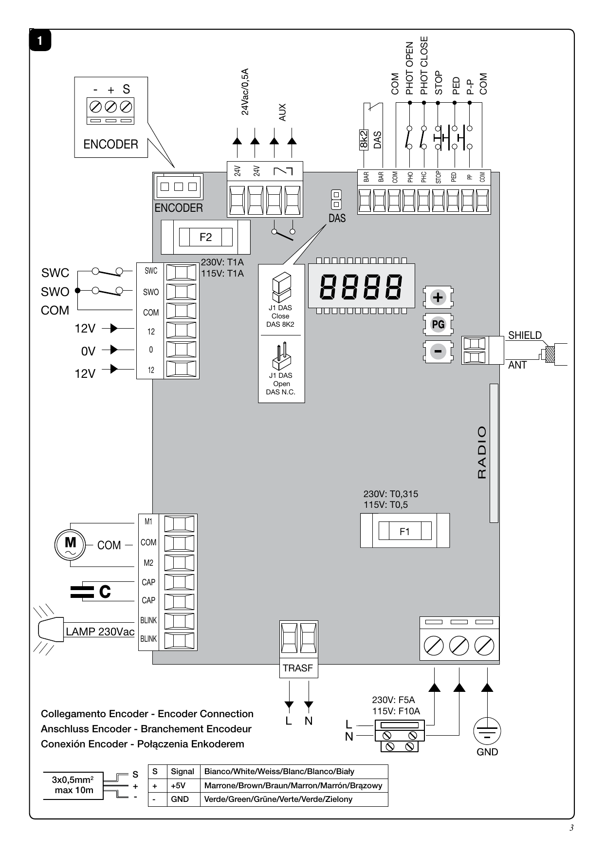
Nella seguente tabella sono descritti i collegamenti elettrici rappresentati in Fig. 1:
| Morsetti | Funzione | Descrizione |
|---|---|---|
| L/N | Alimentazione | CP.BULL8: Ingresso 230Vac 50Hz (L-Fase/N-Neutro). CP.BULL8 115: Ingresso 115Vac 60Hz (L-Fase/N-Neutro) |
| GND | GND | Collegamento messa a terra (obbligatorio) |
| ANT/SHIELD | Antenna | Collegamento antenna scheda radioricevente integrata (ANT-segnale/SHIELD-schermo) |
| COMUNE | +12V | Comune per gli ingressi di comando |
| PP | Passo-Passo | Ingresso pulsante passo-passo (contatto N.O.). Configurabile come ingresso APRE con logica OPCL. |
| PED | PEDONALE | Ingresso pulsante pedonale (contatto N.O.), comanda l'apertura parziale, configurabile dal parametro TPED. Al termine del tempo TCA (se attivato) viene comandata la chiusura. Configurabile come ingresso CHIUDE con logica OPCL. |
| STOP | STOP | Ingresso pulsante STOP (contatto N.C.) |
| PHOT O (PHO) | — | Ingresso (contatto N.C.) per dispositivi di sicurezza (es. fotocellule). In chiusura: l'apertura del contatto provoca l'arresto del motore; quando la fotocellula viene liberata, il motore inverte la direzione (apre). In apertura: l'apertura del contatto provoca l'arresto del motore; quando la fotocellula viene liberata, il motore riparte in apertura. |
| PHOT C (PHA) | — | Ingresso (contatto N.C.) per dispositivi di sicurezza. In chiusura e in apertura: comportamento configurabile dalla logica PHTC. |
| COMUNE | +12V | Comune per gli ingressi di comando |
| BAR/BAR | COSTA | Ingresso contatto costa sensibile (contatto N.C.). Costa resistiva: Jumper "DAS" chiuso; Costa meccanica: Jumper "DAS" aperto. L'intervento della costa arresta il movimento dell'anta e inverte per circa 3s. Se non si utilizza la costa: Jumper "DAS" aperto, ponticello tra i morsetti BAR/BAR. |
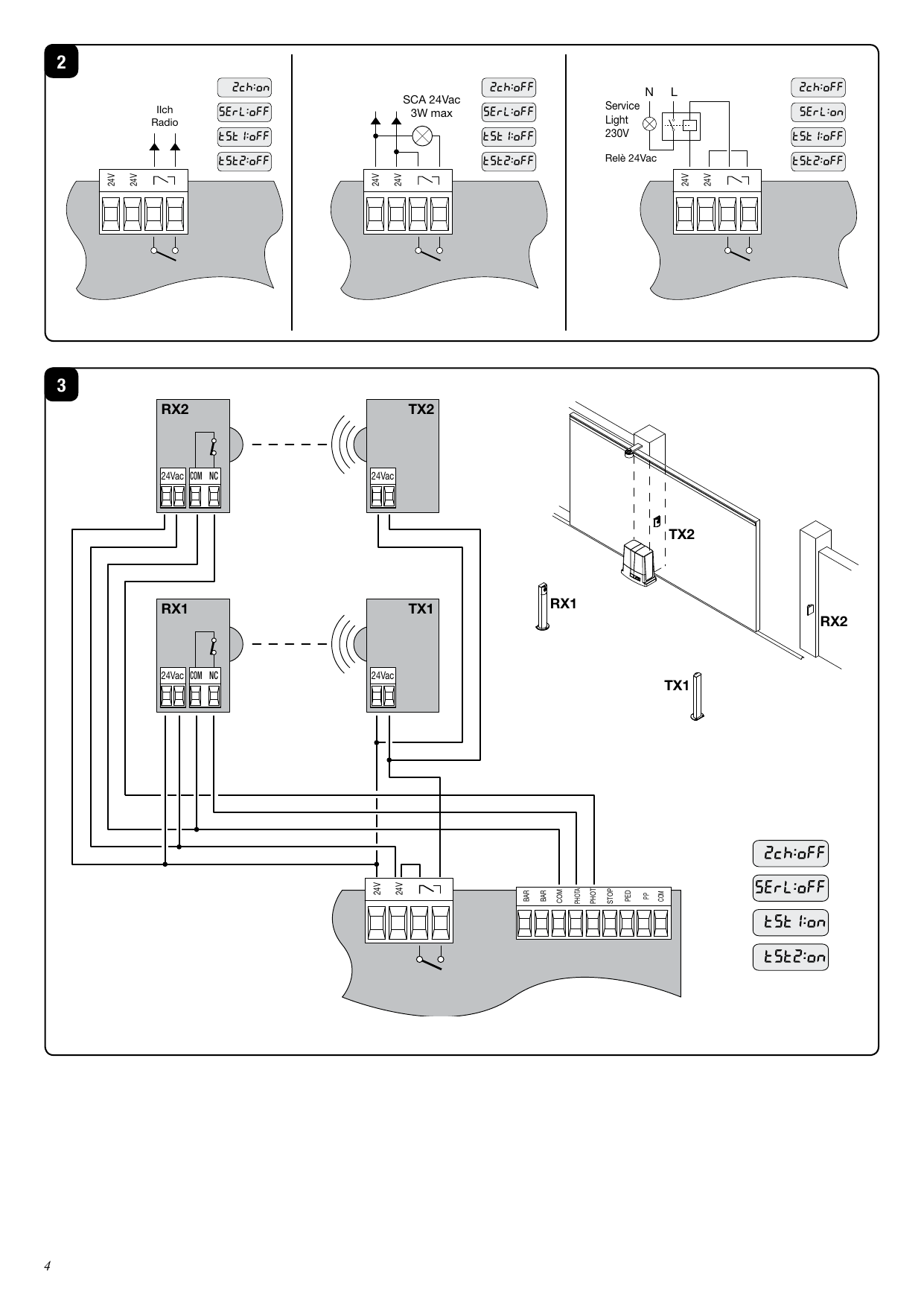
| SCA / Luce di servizio / RX 2° Ch / PHOTO TEST | — | Contatto pulito N.O. Configurabile come: SCA (spia cancello aperto): contatto aperto ad anta chiusa, intermittente veloce in chiusura, intermittente lento in apertura, contatto chiuso ad anta aperta (Logiche 2CH:OFF, SERL:OFF, TST1:OFF, TST2:OFF); Luce di servizio temporizzata (Logica SERL, Fig.2); Uscita secondo canale radio (Logica 2CH, Fig.2); PHOTO TEST per alimentare i trasmettitori delle fotocellule in modalità TEST (Logiche TST1, TST2, Fig.3). |
| 24Vac 24Vac | — | Uscita alimentazione accessori 24Vac/500mA max |
| ENC1 | ENCODER | Connettore per collegamento sensore antischiacciamento (ENCODER) |
| SWC | SWC | Ingresso finecorsa CHIUDE (contatto N.C.) |
| SWO | SWO | Ingresso finecorsa APRE (contatto N.C.) |
| COM | COM (+12V) | Comune per finecorsa |
| 12-0-12 | Secondario | Collegamento avvolgimento secondario trasformatore |
| M1/COM/M2 | Motore | Collegamento motore 230Vac - monofase: M1-Fase/ COM-Comune/ M2-Fase |
| CAP/CAP | Condensatore | Collegamento al condensatore |
| BLINK/BLINK | Lampeggiante | Collegamento lampeggiante 230Vac 40W max. |
| TRASF | Primario | Collegamento avvolgimento primario trasformatore |
Fusibili
- F1 Fusibile di protezione trasformatore
- F2 Fusibile protezione uscita accessori e segnali
Verifica collegamenti
Prima di procedere con la programmazione della centrale, verificare il corretto collegamento del motore:
- Togliere alimentazione.
- Sbloccare manualmente l'anta, portarla a circa metà della corsa e ribloccarla.
- Ripristinare l'alimentazione.
- Dare un comando di passo-passo mediante pulsante <->.
- L'anta deve muoversi in apertura. Nel caso ciò non avvenisse, invertire i collegamenti del motore (M1<>M2) e i finecorsa SWO<>SWC.
- Effettuare una manovra completa da finecorsa a finecorsa, senza interruzioni, per l'apprendimento della corsa.
Programmazione
La programmazione delle varie funzionalità della centrale viene effettuata utilizzando il display LCD presente a bordo della centrale ed impostando i valori desiderati nei menu di programmazione. Il menu parametri consente di impostare un valore numerico ad una funzione, in modo analogo ad un trimmer di regolazione. Il menu logiche consente di attivare o disattivare una funzione, in modo analogo al settaggio di un dip-switch. Altre funzioni speciali seguono i menu parametri e logiche e possono variare a seconda del tipo di centrale o revisione software.
Utilizzo dei pulsanti <PG>/<+>/<->
- Premendo <+> si scorre il menù funzioni dal basso verso l'alto.
- Premendo <-> si scorre il menù funzioni dall'alto verso il basso.
- Premendo <PG> si accede alle impostazioni da modificare.
- Con i tasti <+> e <-> si modificano i valori impostati.
- Ripremendo <PG> il valore viene programmato, il display mostra il segnale "PRG".
Note: La pressione simultanea di <+> e <-> entro un menu funzione consente di tornare al menu superiore senza modifiche. La pressione di <-> a display spento equivale a un comando passo-passo. All'accensione viene visualizzata per circa 5s la versione software. Mantenere la pressione su <+> o <-> per accelerare l'incremento/decremento. Dopo 30s la centrale esce dalla programmazione e spegne il display.
Parametri
| Menu | Funzione | Min-Max-(Default) |
|---|---|---|
| TCA | Tempo di chiusura automatica. Attivo solo con logica "TCA"=ON. Al termine del tempo impostato la centrale comanda una chiusura. | 1-240-(40s) |
| TM | Tempo lavoro motore. Regola il tempo di funzionamento in apertura e chiusura. | 1-250-(90s) |
| Tped | Spazio percorso dall'anta durante l'apertura parziale (pedonale). | 20-250-(50 cm) |
| TSM | Spazio percorso dall'anta durante il rallentamento. 0 = rallentamento disabilitato. | 0-250-(0 cm) |
| PMo | Coppia applicata al motore in apertura.* | 30-99-(40%) |
| PMC | Coppia applicata al motore in chiusura.* | 30-99-(40%) |
| PSo | Coppia applicata al motore durante il rallentamento in apertura.* | 30-99-(50%) |
| PSC | Coppia applicata al motore durante il rallentamento in chiusura.* | 30-99-(50%) |
| SEAV | Soglia di intervento dispositivo antischiacciamento (Encoder) a velocità normale.* 1: max sensibilità - 99: min; 0: intervento a cancello fermo. | 0-99-(0%) |
| SEAR | Soglia di intervento dispositivo antischiacciamento (Encoder) durante il rallentamento.* 1: max sensibilità - 99: min; 0: intervento a cancello fermo. | 0-99-(0%) |
| TLS | Attivo solo con logica SERL:ON. Tempo di attivazione della luce di servizio. | 1-240-(60s) |
| ibra | Forza del freno motore. 0: disabilitata - 1: minima - 99: massima. | 0-99-(50%) |
* ATTENZIONE: Un'errata impostazione di questi parametri può risultare pericolosa. Rispettare le normative vigenti!
Logiche
| Menu | Funzione | Default |
|---|---|---|
| TCA | Abilita/disabilita la chiusura automatica. On: abilitata; Off: disabilitata. | (ON) |
| IBL | Funzione condominiale. On: l'impulso P.P. o del trasmettitore non ha effetto durante l'apertura; Off: disabilitata. | (OFF) |
| SCL | Chiusura rapida. On: con cancello aperto o in movimento, l'intervento della fotocellula provoca la chiusura dopo 3s (attiva solo con TCA:ON); Off: disabilitata. | (OFF) |
| PP | Modalità "Pulsante P.P." e trasmettitore. On: APRE > CHIUDE > APRE; Off: APRE > STOP > CHIUDE > STOP. | (OFF) |
| PRE | Pre-lampeggio. On: il lampeggiante si attiva 3s prima della partenza; Off: disabilitato. | (OFF) |
| LTCA | Lampeggiante durante il tempo TCA. On: attivo; Off: non attivo. | (OFF) |
| CLOC | Modalità ingresso APRE (solo con OPCL:On). On: funzionalità OROLOGIO (contatto chiuso = cancello aperto; contatto aperto = funzionamento normale); Off: funzionalità APRE. | (OFF) |
| HTR | Uomo presente (solo con OPCL:On). On: la pressione di APRE/CHIUDE deve essere mantenuta durante la manovra; Off: automatico. | (OFF) |
| IBCA | Comandi PP e PED durante TCA (solo con OPCL:Off). On: non abilitati; Off: abilitati. | (OFF) |
| ENC | Encoder. On: abilitato; Off: disabilitato. | (ON) |
| CVAR | Trasmettitori a codice programmabile. On: ricevitore abilitato solo a codice variabile (rolling-code); Off: abilitato a rolling-code e programmabile (autoapprendimento e dip/switch). | (OFF) |
| 2CH | Secondo canale radio sui morsetti AUX. On: AUX come secondo canale radio (SERL, TST1, TST2 in OFF); Off: AUX configurabile come SCA o da SERL/TST1/TST2. | (OFF) |
| SERL | Luce di servizio sull'uscita AUX. On: ad ogni manovra il contatto si chiude per il tempo TLS (TST1, TST2, 2CH in OFF); usare un relè ausiliario; Off: AUX configurabile come SCA o da 2CH/TST1/TST2. | (OFF) |
| TST1 | Verifica fotocellule sull'ingresso PHOT O. On: verifica abilitata (se negativa nessuna manovra); Off: AUX configurabile come SCA o da 2CH/SERL/TST2. | (OFF) |
| TST2 | Verifica fotocellule sull'ingresso PHOT C. On: verifica abilitata; Off: AUX configurabile come SCA o da 2CH/SERL/TST1. | (OFF) |
| PHTC | Modalità ingresso PHOT C. On: attivo in apertura e chiusura (in apertura: arresto, alla liberazione riparte in apertura; in chiusura: arresto, alla liberazione inverte/apre); Off: attivo solo in chiusura (arresto e inversione istantanea/apre). | (OFF) |
| OPCL | Ingresso PP come APRE e PED come CHIUDE. On: abilitati; Off: PP e PED attivi con la propria funzione. | (OFF) |
Menu RADIO
| Menu | Funzione |
|---|---|
| PP | La ricevente si pone in attesa (Push) di un codice trasmettitore da assegnare alla funzione passo-passo. Premere il tasto del trasmettitore. Se il codice è valido, viene memorizzato (OK); se non valido (Err). |
| 2Ch | Attesa (Push) di un codice trasmettitore da assegnare al secondo canale radio. Se valido OK, altrimenti Err. |
| CLR | Attesa (Push) di un codice trasmettitore da cancellare. Se valido OK; se non valido o non presente Err. |
| RTR | Cancella completamente la memoria della ricevente. Viene richiesta conferma. |
Altri menu
| Menu | Funzione |
|---|---|
| NMAN | Visualizza il numero di cicli completi (apre+chiude). Prima pressione <PG> mostra le prime 4 cifre, seconda le ultime 4. Es. <PG> 0012 >>> <PG> 3456: 123.456 cicli. |
| RES | RESET della centrale. ATTENZIONE!: Riporta la centrale ai valori di default. Prima pressione <PG> lampeggia "RES", seconda pressione effettua il reset. Nota: non vengono cancellati i trasmettitori, né la posizione e la corsa dell'anta. |
Modalità di funzionamento con Encoder abilitato/disabilitato
Con LOGICA ENC=ON: il sensore antischiacciamento è attivato; regolare la sensibilità con i parametri SEAV e SEAR. Anche una accurata regolazione del freno motore (parametro IBRA) può contribuire al rispetto delle normative. Attivando il rallentamento (TSM da 0 a valore superiore) è necessario effettuare una manovra completa da finecorsa a finecorsa, senza interruzioni, per l'apprendimento della corsa. La corsa viene aggiornata e salvata in memoria con la posizione del cancello in caso di mancanza rete.
Con LOGICA ENC=OFF: il sensore antischiacciamento è disattivato. Se TSM>0 (rallentamento attivato), la prima manovra viene eseguita a velocità normale per l'apprendimento della corsa, anche in caso di mancanza rete.
Diagnostica
Ad ogni ingresso è associato un segmento del display che si accende indicando lo stato (finecorsa, comando e sicurezza). Segmenti: SWO, SWC, P.P., PED, PHOT-O, PHOT, STOP, DAS. Gli ingressi N.C. sono rappresentati dai segmenti verticali; gli ingressi N.O. dai segmenti orizzontali.
Messaggi di errore
- ERR Errore apprendimento corsa oppure memorizzazione telecomandi.
- ERR1 Errore PHOTOTEST PHOT O.
- ERR2 Errore PHOTOTEST PHOT C.
- ERR3 Errore Encoder.
Esempio programmazione
Supponiamo sia necessario impostare un TCA di 100s e attivare il prelampeggio:
| Passo | Premere | Display | Note |
|---|---|---|---|
| 1 | PG | PAr | Primo menu |
| 2 | PG | TCA | Prima funzione del primo menu |
| 3 | PG | 040 | Valore attualmente impostato |
| 4 | + / - | 100 | Settare il valore desiderato |
| 5 | PG | PrG | Il valore viene programmato |
| TCA | Il display si riporta alla funzione settata | ||
| 6 | + - | PAr | Premere simultaneamente per spostarsi al menu superiore |
| 7 | - | Log | Secondo menu |
| 8 | PG | TCA | Prima funzione del secondo menu |
| 9 | - | Pre | Premere più volte fino a selezionare la logica PRE |
| 10 | PG | OFF | Valore attualmente impostato |
| 11 | + / - | ON | Settare il valore desiderato |
| 12 | PG | PrG | Il valore viene programmato |
| Pre | Il display si riporta alla funzione settata | ||
| 13 | + - | PAr | Premere simultaneamente per tornare al menu superiore e uscire o attendere 30s |
Smaltimento
Qualora il prodotto venga posto fuori servizio, è necessario seguire le disposizioni legislative in vigore per lo smaltimento differenziato ed il riciclaggio dei vari componenti (metalli, plastiche, cavi elettrici, ecc.); è consigliabile contattare il vostro installatore o una ditta specializzata ed abilitata allo scopo.
English
Warnings
This manual has been especially written to be used by qualified fitters. None of the information provided in this manual can be considered as being of interest for the end users. Preserve this manual for future needs.
The technician has to furnish all the information related to the step by step function, the manual and the emergency function of the operator, and to deliver the manual to the final user.
- Foresee on the supply net an omnipolar switch or selector with distance of the contacts equal or superior to 3 mm. Verify that of the electrical system there is a differential interrupter and overcurrent protection.
- Some typologies of installation require the connection of the shutter to be linked at a conductive mass of the ground according to the regulations in force.
- The electrical installation and the operating logic must comply with the regulations in force.
- The leads fed with different voltages must be physically separate, or they must be suitably insulated with additional insulation of at least 1 mm.
- The leads must be secured with an additional fixture near the terminals.
- During installation, maintenance and repair, interrupt the power supply before opening the lid to access the electrical parts.
- Check all the connections again before switching on the power.
- The unused N.C. inputs must be bridged.
The descriptions and the present illustrations in this manual are not binding. Leaving the essential characteristics of the product unchanged, the manufacturer reserves the right to bring any change of technical, constructive or commercial character without undertaking to update the present publication.
CE Declaration of Conformity
Declaration in accordance with Directives 2004/108/CE (EMC); 2006/95/CE (LVD). Manufacturer: AUTOMATISMI BENINCÀ SPA, Via Capitello, 45 - 36066 Sandrigo (VI) - Italy. Declares that the product: Control box for 1 motor, ideal for sliding doors: CPBULL8, conforms with the requirements of the following EU Directives:
- Directive 2004/108/CE (15 December 2004, electromagnetic compatibility): EN 61000-6-2:2005, EN 61000-6-3:2007.
- Directive 2006/95/CE (12 December 2006, electrical material in voltage ranges): EN 60335-1:2002 + A1:2004 + A11:2004 + A12:2006 + A2:2006 + A13:2008; EN 60335-1-103:2003.
- As applicable: Directive 1999/5/CE (9 March 1999, radio equipment and telecommunications terminals): ETSI EN 301 489-3 V1.4.1 (2002) + ETSI EN 301 489-1 V1.4.1 (2002) + ETSI EN 300 220-3 V1.1.1 (2000) + EN 60950-1 (2001).
Benincà Luigi, Legal representative. Sandrigo, 02/11/2010.
Technical Data
| Control Unit supply | 230 Vac 50/60 Hz or 115Vac 50/60Hz according to the version |
| Output supply | 1 motor 230Vac |
| Power maximum motor | 280 W |
| Output supply accessories | 24Vac 500mA max. |
| Protection level | IP54 |
| Operating temp. | -20°C / +70°C |
| Radio receiver | built in 433,92 MHz configurable (rolling-code or programmable + rolling-code) |
| Rolling code transmitters supported | 64 rolling-code |
CP.BULL8 Control Unit – Wire Diagram
| Terminals | Function | Description |
|---|---|---|
| L/N | Power supply | CP.BULL8: Input, 230Vac 50Hz (L-Phase/N-Neutral). CP.BULL8 115: Input, 115Vac 60Hz |
| GND | GND | Earth (compulsory) |
| ANT/SHIELD | Antenna | Connection of the antenna to the integrated radio-receiver module (ANT-signal/SHIELD-screen) |
| COMMON | +12V | Common for control inputs |
| PP | Step-by-Step | Input, step-by-step push-button (N.O. contact). Presettable as Input OPEN with OPCL logics. |
| PED | PEDESTRIAN | Input, pedestrian push-button (N.O.). Controls partial opening, configurable through TPED. At end of TCA (if activated) closure control signal is sent. Presettable as Input CLOSE with OPCL. |
| STOP | STOP | Input, STOP push-button (N.C. contact) |
| PHOT O (PHO) | — | Input (N.C.) for safety devices. During closure: contact opening stops motor; with OPCL when photocell is no longer obscured, motor reversion occurs (gate opens). During opening: contact opening stops motor; when released, motor restarts opening. |
| PHOT C (PHA) | — | Input (N.C.) for safety devices. During closure/opening: preset by PHTC logics. |
| +12V | COMMON | Common for control inputs |
| BAR/BAR | SENSITIVE EDGE | Input, safety edge (N.C.). Resistive edge: Jumper "DAS" closed; Mechanical edge: Jumper "DAS" open. If activated, gate stops and reverses for ~3 sec. If not in use: Jumper "DAS" open, jumper between terminals BAR/BAR. |
| SCA / Service light / RX 2° Ch / PHOTO TEST | — | Free N.O. contact. Presettable as: SCA (open gate indicator lamp): open when closed, fast flashing while closing, slow flashing while opening, closed when open (Logics 2CH:OFF, SERL:OFF, TST1:OFF, TST2:OFF); Timed service light (SERL, Fig.2); Output second radio channel (2CH, Fig.2); PHOTO TEST to power photocell transmitters in TEST mode (TST1, TST2, Fig.3). |
| 24Vac 24Vac | — | Output, power supply of accessories, 24Vac/500mA max |
| ENC1 | ENCODER | Connector for connection of anti-crash sensor |
| SWC | SWC | Input, CLOSE limit switch (N.C.) |
| SWO | SWO | Input, OPEN limit switch (N.C.) |
| COM | COM (+12V) | Common for limit switches |
| 12-0-12 | Secondary | Connection of secondary winding of transformer |
| M1/COM/M2 | Motor | Motor connection, 230Vac – single phase: M1-Phase/ COM-Common/ M2-Phase |
| CAP/CAP | Capacitor | Connection to capacitor |
| BLINK/BLINK | Flashing light | Connection to flashing light, 230Vac 40W max. |
| TRASF | Primary | Connection to transformer primary winding |
Fuses
- F1 Output protection fuse for motor and blinker
- F2 Output protection fuse of accessories and signals
To check connections
- Cut off power supply.
- Manually release the gate leaf, move it at approx. half stroke and block it again.
- Power the system again.
- Give a step-by-step control through push-button <->.
- The gate leaf should open. If no movement, invert the motor connections (M1<>M2) and limit switches SWO<>SWC.
- Perform a complete operation, from limit switch to limit switch, without stops, to allow for the gate stroke memorisation.
Programming
The parameters menu allows you to assign a numerical value to a function, like a regulating trimmer. The logic menu allows you to activate or deactivate a function, like setting a dip-switch. Other special functions follow the parameters and logic menus and may vary depending on the type of control unit or the software release.
Use of programming keys
- If <+> is pressed, the Function Menu can be scrolled from top to bottom.
- If <-> is pressed, the Function Menu can be scrolled from bottom to top.
- If <PG> is pressed, presetting to be modified can be entered.
- The preset values can be modified by using <+> and <-> keys.
- The value is programmed if <PG> is pressed again. The word "PRG" appears.
Notes: Simultaneously pressing <+> and <-> from inside a function menu returns to the previous menu without changes. With display off, pressing <-> is like a step-by-step control. At switch-on, software version is displayed for ~5 sec. Hold down <+> or <-> to accelerate. After 30s the control unit quits programming mode and switches off the display.
Parameters
| Menu | Function | Min-Max-(Default) |
|---|---|---|
| TCA | Automatic closure time (only with "TCA"=ON). At end of preset time the unit controls a closure operation. | 1-240-(40s) |
| TM | Operating time during motor opening and closing phases. | 1-250-(90s) |
| Tped | Area covered by the gate during partial opening (pedestrian). | 20-250-(50 cm) |
| Tsm | Area covered during braking. 0 = braking disabled. | 0-250-(0 cm) |
| PMo | Torque applied to motor in opening phase.* | 1-99-(50%) |
| PMC | Torque applied to motor in closing phase.* | 1-99-(50%) |
| Pso | Torque applied during braking (closing phase).* | 1-99-(50%) |
| Psc | Torque applied during braking (opening phase).* | 1-99-(50%) |
| SeaU | Intervention threshold of anti-crashing device (Encoder) at normal speed.* 1: max sensitivity - 99: min. | 0-99-(0%) |
| SEAR | Intervention threshold of anti-crashing device (Encoder) during braking.* 1: max - 99: min. | 0-99-(0%) |
| TLS | Only with SERL:ON. Activation time of the service light. | 1-240-(60s) |
| Ibra | Force of the motor brake. 0: disabled - 1: min - 99: max. | 0-99-(50%) |
* WARNING: An incorrect setting of these parameters may cause danger. Please comply with regulations in force!
Logics
| Menu | Function | Default |
|---|---|---|
| TCA | Automatic closure enabled/disabled. On: enabled; Off: disabled. | (ON) |
| IbL | Multi-flat function. On: P.P. impulse or transmitter has no effect during opening; Off: disabled. | (OFF) |
| SCL | Rapid closure. On: with gate open/moving, photocell activation causes automatic closure after 3s (only with TCA:ON); Off: disabled. | (OFF) |
| PP | Operating mode of "P.P. Push button" and transmitter. On: OPEN > CLOSE > OPEN; Off: OPEN > STOP > CLOSE > STOP. | (OFF) |
| PRE | Forewarning flashing light. On: flashing light activated 3s before motor start; Off: disabled. | (OFF) |
| LTCA | Blinker during TCA. On: activated; Off: de-activated. | (OFF) |
| CLOC | OPEN input mode. On: WATCH function (CLOSED contact - open gate; OPEN contact - normal operation); Off: OPEN function. | (OFF) |
| htr | Operator (man-present) function. On: OPEN/CLOSE push-buttons must be kept pressed; Off: automatic operation. | (OFF) |
| IBCA | PP and PED controls during TCA. On: disabled; Off: enabled. | (OFF) |
| ENC | Encoder. On: enabled, braking activated; Off: disabled, braking deactivated. | (ON) |
| CVAR | Code programmable transmitters. On: receiver enabled only for rolling-code; Off: enabled for rolling-code and programmable (self-learning and Dip Switch). | (OFF) |
| 2CH | Second radio channel on AUX. On: AUX as second radio channel (SERL, TST1, TST2 OFF); Off: AUX preset as SCA or by SERL/TST1/TST2. | (OFF) |
| SERL | Service light on AUX. On: at each operation contact closed for time TLS (TST1, TST2, 2CH OFF), use auxiliary relay; Off: AUX preset as SCA or by 2CH/TST1/TST2. | (OFF) |
| TST1 | Check photocells on PHOT O. On: enabled (if unsuccessful, no operation); Off: AUX preset as SCA or by 2CH/SERL/TST2. | (OFF) |
| TST2 | Check photocells on PHOT C. On: enabled; Off: AUX preset as SCA or by 2CH/SERL/TST1. | (OFF) |
| PHTC | PHOT C input mode. On: activated in opening and closing; Off: activated in closing only (contact opening stops motor and immediate reversion/open). | (OFF) |
| OPCL | PP as OPEN and PED as CLOSED. On: enabled; Off: PP and PED with their function. | (OFF) |
RADIO menu
| Menu | Function |
|---|---|
| PP | Receiver awaits (Push) a transmitter code for step-by-step function. If valid OK, else Err. |
| 2Ch | Receiver awaits a transmitter code for second radio channel. If valid OK, else Err. |
| CLR | Receiver awaits a transmitter code to be erased. If valid OK; if not valid/not in memory Err. |
| RTR | Completely erase the receiver memory. Confirmation of operation is required. |
Other menus
| Menu | Function |
|---|---|
| NMAN | Number of cycles (open+close) completed. First <PG> press: first 4 digits; second press: last 4. E.g. <PG> 0012 >>> <PG> 3456: 123.456 cycles. |
| RES | RESET of control unit. WARNING: resets to default values. First <PG> press: "RES" flashes; second press: reset. Note: transmitter codes, position and stroke are not erased. |
Operating mode with enabled/disabled Encoder
ENC=ON: anti-crash sensor activated; adjust sensitivity through SEAV and SEAR. An accurate adjustment of the motor brake (IBRA) may help compliance. If braking activated (TSM from 0 to higher value), perform a complete operation limit-to-limit without stops for stroke memorisation. In power failure, stroke is updated and stored with gate position.
ENC=OFF: anti-crash sensor disabled. If TSM>0, first operation performed at normal speed for stroke memorisation, even in power failure.
Diagnostics
Each input is matched with a display segment that switches on to indicate the status (limit switches, control and safety): SWO, SWC, P.P., PED, PHOT-O, PHOT, STOP, DAS. N.C. inputs are represented by vertical segments; N.O. inputs by horizontal segments.
Error messages
- ERR Error, stroke self-learning or remote control code memorisation.
- ERR1 Error, PHOTOTEST PHOT O.
- ERR2 Error, PHOTOTEST PHOT C.
- ERR3 Error, Encoder.
Example of programming
To set an automatic closing time (TCA) of 100s and activate pre-blinking, follow the same step sequence shown in the Italian section (PAr → TCA → 040 → 100 → PrG; then Log → PrE → OFF → ON → PrG).
Waste disposal
If the product must be dismantled, it must be disposed according to regulations in force regarding the differentiated waste disposal and the recycling of components (metals, plastics, electric cables, etc.). For this operation it is advisable to call your installer or a specialised company.
Deutsch
Hinweise
Dieses Handbuch ist ausschließlich qualifiziertem Personal für die Installation und Wartung von automatischen Öffnungsvorrichtungen bestimmt. Es enthält keine Informationen, die für den Endbenutzer nützlich sein könnten. Bewahren Sie dieses Handbuch auf.
Der Installateur hat dem Benutzer alle Informationen über den automatischen, manuellen und Not-Betrieb der Automatik zusammen mit der Bedienungsanleitung zu liefern.
- Das Stromnetz muss mit einem allpoligen Schalter bzw. Trennschalter ausgestattet sein, dessen Kontakte einen Öffnungsabstand gleich oder größer als 3 mm aufweisen. Kontrollieren, ob der elektrischen Anlage ein geeigneter Differentialschalter und ein Überspannungsschutzschalter vorgeschaltet sind.
- Einige Installationstypologien verlangen den Anschluss des Flügels an eine Erdungsanlage laut den geltenden Sicherheitsnormen.
- Die elektrische Installation und die Betriebslogik müssen den geltenden Vorschriften entsprechen.
- Die mit unterschiedlichen Spannungen gespeisten Leiter müssen physisch getrennt oder mit zusätzlicher Isolierung von mindestens 1 mm isoliert werden.
- Die Leiter müssen in der Nähe der Klemmen zusätzlich befestigt werden.
- Während der Installation, Wartung und Reparatur die Anlage stromlos machen, bevor an den elektrischen Teilen gearbeitet wird.
- Alle Anschlüsse nochmals prüfen, bevor die Zentrale mit Strom versorgt wird.
- Die nicht verwendeten N.C. Eingänge müssen überbrückt werden.
Die in diesem Handbuch enthaltenen Beschreibungen und Abbildungen sind nicht verbindlich. Der Hersteller behält sich das Recht vor, technische, konstruktive oder kommerzielle Änderungen vorzunehmen.
CE-Konformitätserklärung
Erklärung im Einklang mit den Richtlinien 2004/108/CE(EMC); 2006/95/CE(LVD). Hersteller: Automatismi Benincà SpA, Via Capitello, 45 - 36066 Sandrigo (VI) - Italien. Erklärt, dass das Produkt: Steuerung für 1 Motor, ideal für Schiebetore: CPBULL8, die folgenden CE-Richtlinien erfüllt: 2004/108/CE (EN 61000-6-2:2005, EN 61000-6-3:2007); 2006/95/CE (EN 60335-1:2002 + A1:2004 + A11:2004 + A12:2006 + A2:2006 + A13:2008; EN 60335-1-103:2003); falls anwendbar 1999/5/CE (ETSI EN 301 489-3 V1.4.1, ETSI EN 301 489-1 V1.4.1, ETSI EN 300 220-3 V1.1.1, EN 60950-1). Benincà Luigi, Leiter der Rechtsabteilung. Sandrigo, 02.11.2010.
Technische Daten
| Stromversorgung | 230 Vac 50/60 Hz oder 115Vac 50/60Hz je nach Ausführung |
| Motorausgang | 1 Motor 230Vac |
| Maximale Motorenleistung | 280 W |
| Ausgang Speisung Zubehör | 24Vac 500mA max. |
| Schutzklasse | IP54 |
| Betriebstemperatur | -20°C / +70°C |
| Funkempfänger | 433,92 MHz eingebaut und konfigurierbar (Rolling-Code oder fest+Rolling-Code) |
| Programmierbare Codes | 64 rolling-code |
Steuereinheit CP.BULL8 – Elektrische Anschlüsse
| Klemmen | Funktion | Beschreibung |
|---|---|---|
| L/N | Speisung | CP.BULL8: Eingang 230Vac 50Hz (L-Phase/N-Nulleiter). CP.BULL8 115: Eingang 115Vac 60Hz |
| GND | GND | Zur Erdung (vorgeschrieben) |
| ANT/SHIELD | Antenne | Anschluss Antenne Karte integrierter Funkempfänger (ANT-Signal/SHIELD-Schirm) |
| GEMEIN | +12V | Gemein für alle Steuerungseingänge |
| PP | Schritt-Schritt | Eingang Taste Schritt-Schritt (Kontakt N.O.). Als Eingang ÖFFNEN mit Logik OPCL konfigurierbar. |
| PED | FUSSGÄNGER | Eingang Taste Fußgänger (Kontakt N.O.), steuert das teilweise Öffnen (Parameter TPED). Nach Ablauf von TCA (wenn aktiv) wird das Schließen gesteuert. Als Eingang SCHLIESSEN mit Logik OPCL konfigurierbar. |
| STOP | STOP | Eingang Taste STOP (Kontakt N.C.) |
| PHOT O (PHO) | — | Eingang (Kontakt N.C.) für Sicherheitsvorrichtungen. Beim Schließen: Kontaktöffnung hält den Motor an; bei Freisetzung der Fotozelle schaltet der Motor um (öffnet). Beim Öffnen: Anhalten; bei Freisetzung schaltet wieder zum Öffnen ein. |
| PHOT C (PHA) | — | Eingang (Kontakt N.C.). Beim Schließen/Öffnen: Verhalten durch Logik PHTC konfigurierbar. |
| GEMEIN | +12V | Gemein für alle Steuerungseingänge |
| BAR/BAR | FLANKE | Eingang Kontakt Näherungsflanke (N.C.). Widerstandsfähige Flanke: Jumper "DAS" geschlossen; Mechanische Flanke: Jumper "DAS" geöffnet. Einschalten der Flanke hält den Flügel an und schaltet ca. 3 sec. um. Wird die Flanke nicht verwendet: Jumper "DAS" geöffnet, Brücke zwischen BAR/BAR. |
| SCA / Dienstlicht / RX 2° Ch / PHOTO TEST | — | Reiner Kontakt N.O. Konfigurierbar als: SCA (Meldeleuchte Tor offen), zeitgesteuertes Dienstlicht (Logik SERL), Ausgang zweiter Funkkanal (Logik 2CH), PHOTO TEST (Logik TST1, TST2). |
| 24Vac 24Vac | — | Ausgang Speisung Zubehör 24Vac/500mA max. |
| ENC1 | ENCODER | Verbinder für den Anschluss des Quetschsicherheitssensors |
| SWC | SWC | Eingang Endschalter SCHLIESSEN (Kontakt N.C.) |
| SWO | SWO | Eingang Endschalter ÖFFNEN (Kontakt N.C.) |
| COM | COM (+12V) | Gemein für Endschalter |
| 12-0-12 | Sekundär | Anschluss Wicklung des sekundären Transformators |
| M1/COM/M2 | Motor | Anschluss an den Motor 230Vac – einphasig: M1-Phase/ COM-Gemein/ M2-Phase |
| CAP/CAP | Kondensator | Anschluss an den Kondensator |
| BLINK/BLINK | Blinkleuchte | Anschluss Blinkleuchte 230Vac 40W max. |
| TRASF | Primär | Anschluss Wicklung des primären Transformators |
Sicherungen
- F1 Schutzsicherung Ausgang Motor und Blinkleuchte
- F2 Schutzsicherung Eingang Zubehör und Signale
Anschlüsse überprüfen
- Stromversorgung abtrennen.
- Von Hand die Flügel entsichern, auf halben Hub bringen und wieder blockieren.
- Stromversorgung wieder herstellen.
- Eine Schritt-Schritt-Steuerung durch die Taste <-> geben.
- Die Tür muss sich öffnen. Andernfalls Leiter des Motors (M1<>M2) mit den Endschaltern SWO<>SWC vertauschen.
- Eine komplette Bewegung von Endschalter zu Endschalter ohne Unterbrechung durchführen, um den Hub zu speichern.
Programmierung
Das Menü Parameter ordnet einer Funktion einen numerischen Wert zu (wie ein Trimmer). Das Menü der Logik aktiviert oder deaktiviert eine Funktion (wie ein Dip-Schalter). Gebrauch der Tasten: <+> rollt das Menü von oben nach unten; <-> von unten nach oben; <PG> ruft Einstellungen ab; mit <+>/<-> Werte ändern; nochmals <PG> programmiert (Anzeige "PRG"). Beim Einschalten wird ca. 5 s die Softwareversion angezeigt. Nach 30s verlässt die Zentrale die Programmierung.
Parameter
| Menü | Funktion | Min-Max-(Default) |
|---|---|---|
| TCA | Zeit für das automatische Schließen (nur mit Logik "TCA"=ON). | 1-240-(40s) |
| TM | Betriebszeit während Öffnen und Schließen. | 1-250-(90s) |
| Tped | Weg des Flügels beim teilweisen Öffnen (Fußgänger). | 20-250-(50 cm) |
| Tsm | Weg in der Soft-Stop-Phase. 0 = deaktiviert. | 0-250-(0 cm) |
| PMo | Drehmoment beim Öffnen.* | 1-99-(50%) |
| PMC | Drehmoment beim Schließen.* | 1-99-(50%) |
| Pso | Drehmoment während Geschwindigkeitsabnahme beim Öffnen.* | 1-99-(50%) |
| Psc | Drehmoment während Geschwindigkeitsabnahme beim Schließen.* | 1-99-(50%) |
| SeaU | Empfindlichkeit der Kraftabschaltung (Encoder) bei normaler Geschwindigkeit.* 1: max - 99: min. | 0-99-(0%) |
| SEAR | Empfindlichkeit der Kraftabschaltung (Encoder) im Soft-Lauf. 1: max - 99: min. | 0-99-(0%) |
| TLS | Nur mit Logik SERL:ON. Aktivierungsdauer der externen Beleuchtung. | 1-240-(60s) |
| Ibra | Kraft der Motorenbremse. 0: deaktiviert - 1: min - 99: max. | 0-99-(50%) |
* ACHTUNG: Eine falsche Einstellung dieser Parameter kann gefährlich sein. Die geltenden Vorschriften beachten!
Logik
| Menü | Funktion | Default |
|---|---|---|
| TCA | Automatischer Schließvorgang. On: aktiviert; Off: deaktiviert. | (ON) |
| IbL | Funktion Wohngemeinschaft. On: aktiviert (Impulse haben beim Öffnen keinen Einfluss); Off: deaktiviert. | (OFF) |
| SCL | Schnelles Schließen. On: bei offenem/bewegtem Tor schließt nach 3s (nur mit TCA:ON); Off: deaktiviert. | (OFF) |
| PP | Betriebsweise Taste P.P. und Sendegerät. On: ÖFFNEN > SCHLIESSEN > ÖFFNEN; Off: ÖFFNEN > STOP > SCHLIESSEN > STOP. | (OFF) |
| PRE | Vorblinken. On: 3 sec vor dem Einschalten des Motors; Off: deaktiviert. | (OFF) |
| LTCA | Blinklicht während TCA. On: aktiv; Off: nicht aktiv. | (OFF) |
| CLOC | Betriebsweise Eingang ÖFFNEN. On: UHR-Funktion; Off: Funktion ÖFFNEN. | (OFF) |
| htr | Funktion "Mann vorhanden". On: Taste muss gedrückt bleiben; Off: automatisch. | (OFF) |
| IBCA | Steuerungen PP und PED während TCA. On: nicht aktiviert; Off: aktiviert. | (OFF) |
| ENC | Encoder. On: aktiviert (Soft Stop und Hinderniserkennung aktiv); Off: deaktiviert. | (ON) |
| CVAR | Sendegeräte mit programmierbarem Code. On: nur Rolling-Code; Off: Rolling-Code und programmierbar. | (OFF) |
| 2CH | Zweiter Funkkanal an Klemmen AUX. On: AUX als zweiter Funkkanal (SERL, TST1, TST2 OFF); Off: AUX als SCA oder via SERL/TST1/TST2. | (OFF) |
| SERL | Dienstlicht am Ausgang AUX. On: Kontakt für Zeit TLS geschlossen (TST1, TST2 OFF), Hilfsrelais verwenden; Off: AUX als SCA oder via 2CH/TST1. | (OFF) |
| TST1 | Prüfung Fotozelle Eingang PHOT O. On: aktiviert; Off: AUX als SCA oder via 2CH/TST1/TST2. | (OFF) |
| TST2 | Prüfung Fotozelle Eingang PHOT C. On: aktiviert; Off: AUX als SCA oder via 2CH/TST1. | (OFF) |
| PHTC | Betriebsweise Eingang PHOT C. On: aktiv beim Öffnen und Schließen; Off: aktiv nur beim Schließen (Anhalten und sofortiges Umschalten/öffnet). | (OFF) |
| OPCL | Eingang PP als ÖFFNEN und PED als SCHLIESSEN. On: aktiviert; Off: eigene Funktion. | (OFF) |
FUNK / weitere Menüs
| Menü | Funktion |
|---|---|
| PP | Empfänger wartet (Push) auf einen Sendercode für die Schritt-Schritt-Funktion. Gültig: OK; ungültig: Err. |
| 2Ch | Empfänger wartet auf Sendercode für den zweiten Funkkanal. Gültig: OK; ungültig: Err. |
| CLR | Empfänger wartet auf zu löschenden Sendercode. Gültig: OK; ungültig/nicht gespeichert: Err. |
| RTR | Löscht den gesamten Speicher des Empfängers. Bestätigung erforderlich. |
| NMAN | Zeigt die Anzahl der Zyklen (öffnen + schließen). Erste <PG>: erste 4 Zahlen; zweite: letzte 4. Bsp.: <PG> 0012 >>> <PG> 3456: 123.456 Zyklen. |
| RES | Reset der Zentrale. ACHTUNG! Stellt die Default-Werte wieder ein. Erste <PG>: "RES" blinkt; zweite: Reset. Bemerkung: Sendegeräte, Position und Flügelhub werden nicht gelöscht. |
Betriebsweise mit aktiviertem/deaktiviertem Encoder
ENC=ON: Quetschsicherheitssensor aktiviert; Empfindlichkeit über SEAV und SEAR einstellen. Bei aktivierter Geschwindigkeitsabnahme (TSM > 0) eine vollständige Steuerung von Endschalter zu Endschalter ohne Unterbrechungen vornehmen, um den Flügelhub zu speichern. Der Hub wird mit der Torposition bei Stromausfall gespeichert.
ENC=OFF: Quetschsicherheitssensor deaktiviert. Wenn TSM>0, erfolgt die erste Steuerung bei normaler Geschwindigkeit, auch bei Stromausfall.
Diagnose
Jedem Eingang ist ein Displaysegment zugeteilt (Endschalter, Steuerung und Sicherheit): SWO, SWC, P.P., PED, PHOT-O, PHOT, STOP, DAS. Den N.C.-Eingängen entsprechen die vertikalen Segmente, den N.O.-Eingängen die horizontalen Segmente.
Fehlermeldungen
- ERR Fehler Selbstlernfunktion oder Speichern der Fernbedienungen.
- ERR1 Fehler PHOTOTEST PHOT O.
- ERR2 Fehler PHOTOTEST PHOT C.
- ERR3 Fehler Encoder.
Entsorgung
Wird das Gerät außer Betrieb gesetzt, müssen die gültigen Gesetzesvorschriften zur differenzierten Entsorgung und Wiederverwendung der Einzelkomponenten (Metall, Plastik, Elektrokabel, usw.) beachtet werden. Rufen Sie Ihren Installateur oder eine Entsorgungsfirma.
Français
Recommandations générales
Ce manuel est destiné exclusivement au personnel qualifié pour l'installation et la maintenance des ouvertures automatiques. Aucune information donnée dans ce manuel ne sera d'intérêt ou d'utilité à l'utilisateur final. Conservez ce manuel pour de futures utilisations.
L'installateur doit donner tout renseignement relatif au fonctionnement automatique, manuel et de secours de l'automatisme, et consigner à l'utilisateur du produit le livret d'instructions.
- Il faut prévoir dans le réseau d'alimentation un interrupteur/sectionneur omnipolaire avec une distance d'ouverture des contacts égale ou supérieure à 3 mm. Vérifier la présence en amont d'un disjoncteur différentiel et d'une protection contre la surintensité adéquats. Si nécessaire, raccorder la porte ou le portail motorisé à une installation de mise à la terre conforme aux normes de sécurité en vigueur.
- L'installation électrique et la logique de fonctionnement doivent être conformes aux normes en vigueur.
- Les conducteurs alimentés à des tensions différentes doivent être séparés physiquement ou isolés avec une gaine supplémentaire d'au moins 1 mm.
- Les conducteurs doivent être assurés par une fixation supplémentaire à proximité des bornes.
- Pendant toute intervention d'installation, maintenance et réparation, couper l'alimentation avant de toucher les parties électriques.
- Recontrôler toutes les connexions faites avant d'alimenter la logique de commande.
- Les entrées N.F. non utilisées doivent être shuntées.
Les descriptions et illustrations contenues dans ce manuel ne sont pas contraignantes. Le fabricant se réserve le droit d'apporter n'importe quelle modification technique, de construction ou commerciale.
Déclaration de conformité CE
Déclaration en accord avec les Directives 2004/108/CE(CEM); 2006/95/CE(DBT). Fabricant: Automatismi Benincà SpA, Via Capitello, 45 - 36066 Sandrigo (VI) - ITALIE. Déclare que le produit: Centrale de commande pour 1 moteur, idéale pour portes coulissantes: CPBULL8, est conforme aux Directives CE: 2004/108/CE (EN 61000-6-2:2005, EN 61000-6-3:2007); 2006/95/CE (EN 60335-1:2002 + A1:2004 + A11:2004 + A12:2006 + A2:2006 + A13:2008; EN 60335-1-103:2003); si applicable 1999/5/CE (ETSI EN 301 489-3 V1.4.1, ETSI EN 301 489-1 V1.4.1, ETSI EN 300 220-3 V1.1.1, EN 60950-1). Benincà Luigi, Responsable légal. Sandrigo, 02/11/2010.
Données techniques
| Alimentation du réseau | 230 Vac 50/60 Hz ou 115Vac 50/60Hz selon la version |
| Sortie Moteur | 1 moteur 230Vac |
| Puissance maximale moteur | 280 W |
| Sortie alimentation accessoires | 24Vac 500mA max. |
| Degré de protection | IP54 |
| Temp. de fonctionnement | -20°C / +70°C |
| Récepteur | Incorporé et configurable 433,92 MHz (rolling-code ou fixe+rolling-code) |
| Quantité des codes mémorisables | 64 rolling-code |
Centrale de commande CP.BULL8 – Branchements électriques
| Bornes | Fonction | Description |
|---|---|---|
| L/N | Alimentation | CP.BULL8: entrée 230VCA 50Hz (L-Phase/N-Neutre). CP.BULL8 115: entrée 115VCA 60Hz |
| GND | GND | Raccordement mise à la terre (obligatoire) |
| ANT/SHIELD | Antenne | Branchement antenne carte récepteur radio intégrée (ANT-signal/SHIELD-écran) |
| COMMUN | +12V | Commun pour les entrées de commande |
| PP | Pas à pas | Entrée bouton pas à pas (contact N.O.). Programmable comme entrée OUVRE avec logique OPCL. |
| PED | PIÉTON | Entrée bouton piéton (contact N.O.), commande l'ouverture partielle (paramètre TPED). À la fin du temps TCA (si activé) la fermeture est commandée. Programmable comme entrée FERME avec logique OPCL. |
| STOP | STOP | Entrée bouton STOP (contact N.C.) |
| PHOT O (PHO) | — | Entrée (contact N.C.) pour dispositifs de sécurité. En fermeture: l'ouverture du contact provoque l'arrêt du moteur; quand la photocellule est libérée, le moteur inverse (ouvre). En ouverture: arrêt; quand libérée, le moteur repart en ouverture. |
| PHOT C (PHA) | — | Entrée (contact N.C.) pour dispositifs de sécurité. En fermeture/ouverture: comportement programmable avec la logique PHTC. |
| COMMUN | +12V | Commun pour les entrées de commande |
| BAR/BAR | BOURRELET | Entrée contact barre palpeuse (contact N.F.). Bourrelet résistif: Jumper "DAS" fermé; Bourrelet mécanique: Jumper "DAS" ouvert. L'intervention du bourrelet arrête le mouvement et inverse pendant environ 3s. Si non utilisé: Jumper "DAS" ouvert, pontet entre les bornes BAR/BAR. |
| SCA / Lumière de service / RX 2° Ch / PHOTO TEST | — | Contact net N.O. Programmable comme: SCA (voyant portail ouvert), Lumière de service temporisée (logique SERL), Sortie second canal radio (logique 2CH), PHOTO TEST (logiques TST1, TST2). |
| 24Vac | 24VCA | Sortie alimentation accessoires 24VCA/500mA max |
| ENC1 | CODEUR | Connecteur pour raccordement capteur contre l'écrasement |
| SWC | SWC | Entrée fin de course FERME (contact N.C.) |
| SWO | SWO | Entrée fin de course OUVRE (contact N.C.) |
| COM | COM (+12V) | Commun pour fin de course |
| 12-0-12 | Secondaire | Raccordement enroulement secondaire transformateur |
| M1/COM/M2 | Moteur | Raccordement moteur 230VCA – monophasé: M1-phase/ COM-Commun/ M2-phase |
| CAP/CAP | Condensateur | Raccordement au condensateur |
| BLINK/BLINK | Clignotant | Raccordement clignotant 230VCA 40W max. |
| TRASF | Primaire | Raccordement enroulement primaire transformateur |
Plombs
- F1 Plomb de protection sortie moteur et clignotant
- F2 Plomb de protection sortie accessoires et signaux
Vérification branchements
- Coupez l'alimentation.
- Déloquez manuellement le vantail, portez-le environ à mi-chemin de la course et bloquez-le à nouveau.
- Rétablissez l'alimentation électrique.
- Donner un ordre de pas à pas avec la touche <->.
- Le vantail doit bouger en ouverture. Sans résultat, inverser les raccordements du moteur (M1<>M2) et les fins de course SWO<>SWC.
- Effectuer une manœuvre complète de fin de course à fin de course, sans interruptions, pour l'apprentissage de la course.
Programmation
Le menu paramètres permet d'associer une valeur numérique à une fonction (comme un trimmer). Le menu des logiques permet d'activer ou désactiver une fonction (comme un dip-switch). Touches: <+> défile du haut vers le bas; <-> du bas vers le haut; <PG> accède aux saisies; modifier avec <+>/<->; appuyer de nouveau sur <PG> programme la valeur ("PRG"). À l'allumage, la version logicielle s'affiche pendant environ 5 s. Après 30s, la logique sort du mode programmation.
Paramètres
| Menu | Fonction | Min-Max-(Default) |
|---|---|---|
| TCA | Temps de fermeture automatique (uniquement avec logique "TCA"=ON). | 1-240-(40s) |
| tm | Temps travail moteur (ouverture et fermeture). | 1-250-(90s) |
| Tped | Espace couvert par le vantail durant l'ouverture partielle (accès piétons). | 20-250-(50 cm) |
| Tsm | Espace couvert durant le ralentissement. 0 = ralentissement invalidé. | 0-250-(0 cm) |
| PMo | Couple appliqué au moteur durant l'ouverture.* | 1-99-(50%) |
| PMC | Couple appliqué au moteur durant la fermeture.* | 1-99-(50%) |
| Pso | Couple appliqué durant le ralentissement en ouverture.* | 1-99-(50%) |
| Psc | Couple appliqué durant le ralentissement en fermeture.* | 1-99-(50%) |
| SeaU | Seuil d'intervention du dispositif anti-écrasement (Encoder) à vitesse normale.* 1: max - 99: min. | 0-99-(0%) |
| SEAR | Seuil d'intervention du dispositif anti-écrasement (Encoder) durant le ralentissement.* 1: max - 99: min. | 0-99-(0%) |
| TLS | Uniquement avec logique SERL:ON. Temps d'activation de la lumière de service. | 1-240-(60s) |
| Ibra | Force du frein moteur. 0: invalidé - 1: min - 99: max. | 0-99-(50%) |
* ATTENTION: Une saisie incorrecte de ces paramètres peut s'avérer très dangereuse. Respectez les normes en vigueur!
Logiques
| Menu | Fonction | Default |
|---|---|---|
| TCA | Fermeture automatique. On: validée; Off: invalidée. | (ON) |
| IbL | Fonction copropriété. On: l'impulsion P.P. ou du transmetteur n'a aucun effet durant l'ouverture; Off: invalidée. | (OFF) |
| SCL | Fermeture rapide. On: avec portail ouvert/en mouvement, la photocellule provoque la fermeture après 3 s (uniquement avec TCA:ON); Off: invalidée. | (OFF) |
| PP | Modalité bouton P.P. et transmetteur. On: OUVRE > FERME > OUVRE; Off: OUVRE > STOP > FERME > STOP. | (OFF) |
| PRE | Pré clignotement. On: 3s avant le départ du moteur; Off: invalidé. | (OFF) |
| LTCA | Clignotant durant le temps TCA. On: actif; Off: non actif. | (OFF) |
| CLOC | Modalité entrée OUVRE. On: fonction MONTRE (contact fermé - portail ouvert, contact ouvert - fonctionnement normal); Off: fonction OUVRE. | (OFF) |
| htr | Fonction Homme mort. On: la pression des boutons OUVRE/FERME doit être gardée durant la manœuvre; Off: automatique. | (OFF) |
| IBCA | Commandes PP et PED durant TCA. On: non validées; Off: validées. | (OFF) |
| ENC | Encodeur. On: validé, ralentissement validé; Off: invalidé. | (ON) |
| tri | Contrôle intégrité du TRIAC. On: actif (si TRIAC en panne, le moteur ne démarre pas); Off: pas de contrôle. | (OFF) |
| CVAR | Transmetteurs à code programmable. On: récepteur uniquement rolling-code; Off: rolling-code et programmable (auto-apprentissage et dip/switch). | (OFF) |
| 2CH | Second canal radio sur bornes AUX. On: AUX comme second canal radio (SERL, TST1, TST2 OFF); Off: AUX comme SCA ou par SERL/TST1/TST2. | (OFF) |
| SERL | Lumière de service sortie AUX. On: contact fermé pendant le temps TLS (TST1, TST2 OFF), relais auxiliaire; Off: AUX comme SCA ou par 2CH/TST1/TST2. | (OFF) |
| TST1 | Vérification photocellules entrée PHOT O. On: validée; Off: AUX comme SCA ou par 2CH/SERL/TST2. | (OFF) |
| TST2 | Vérification photocellules entrée PHOT C. On: validée; Off: AUX comme SCA ou par 2CH/SERL/TST1. | (OFF) |
| PHTC | Modalité entrée PHOT C. On: active en ouverture et fermeture; Off: active uniquement en fermeture (arrêt et demi-tour instantané/ouvre). | (OFF) |
| OPCL | Entrée PP comme OUVRE et PED comme FERME. On: habilités; Off: fonction propre. | (OFF) |
RADIO et autres menus
| Menu | Fonction |
|---|---|
| PP | Le récepteur se met en attente (Push) d'un code transmetteur à affecter à la fonction pas-à-pas. Valide: OK; non valide: Err. |
| 2Ch | Attente d'un code transmetteur à affecter au deuxième canal radio. Valide: OK; non valide: Err. |
| CLR | Attente d'un code transmetteur à supprimer de la mémoire. Valide: OK; non valide/absent: Err. |
| RTR | Annule complètement la mémoire du récepteur. Confirmation demandée. |
| NMAN | Affiche le nombre de cycles complets (ouvre+ferme). Première <PG>: 4 premiers chiffres; deuxième: 4 derniers. Ex. <PG> 0012 >>> <PG> 3456: 123.456 cycles. |
| RES | Réinitialisation de la centrale. ATTENTION!: ramène aux valeurs de défaut. Première <PG>: clignotement "RES"; deuxième: réinitialisation. Note: les transmetteurs, la position et la course du vantail ne sont pas annulés. |
Modalité de fonctionnement avec codeur autorisé/coupé
ENC=ON: le capteur contre l'écrasement est activé; régler la sensibilité avec SEAV et SEAR. Si le ralentissement est activé (TSM de 0 à valeur supérieure), faire une manœuvre complète de fin de course à fin de course, sans interruption, pour l'apprentissage de la course. La course est mise à jour et en mémoire avec la position du portail en cas de panne d'électricité.
ENC=OFF: le capteur contre l'écrasement est désactivé. Si TSM>0, la première manœuvre se fait à vitesse normale pour l'apprentissage, même en cas de manque d'électricité.
Diagnostic
Chaque entrée est associée à un segment de l'afficheur (fin de course, commande et sécurité): SWO, SWC, P.P., PED, PHOT-O, PHOT, STOP, DAS. Les entrées N.F. sont représentées par les segments verticaux; les entrées N.O. par les segments horizontaux.
Messages d'erreur
- ERR Erreur apprentissage course ou mise en mémoire des télécommandes.
- ERR1 Erreur PHOTOTEST PHOT O.
- ERR2 Erreur PHOTOTEST PHOT C.
- ERR3 Erreur codeur.
Démolition
Au cas où le produit serait mis hors service, il est impératif de se conformer aux lois en vigueur concernant l'élimination différenciée et le recyclage des différents composants (métaux, matières plastiques, câbles électriques, etc.). Contactez votre installateur ou une firme spécialisée autorisée à cet effet.
Español
Advertencias
Este manual está destinado exclusivamente a personal cualificado para la instalación y el mantenimiento de aperturas automáticas. Ninguna información de las aquí presentadas es de interés o de utilidad para el usuario final. Guardar este manual para futuras consultas.
El instalador debe proporcionar todas las informaciones relativas al funcionamiento automático, manual y de emergencia de la automatización y entregar al usuario de la instalación las instrucciones de uso.
- Prever en la red de alimentación un interruptor/cortacircuitos omnipolar con distancia de apertura de los contactos igual o mayor que 3 mm. Comprobar que entre el aparato y la red eléctrica general haya un interruptor diferencial y una protección contra sobrecorriente adecuados.
- Algunos tipos de instalación requieren conectar la hoja con una instalación de puesta a tierra conforme a las normas de seguridad vigentes.
- La instalación eléctrica y la lógica de funcionamiento deben cumplir las normas vigentes.
- Los conductores alimentados con tensiones distintas deben estar físicamente separados o adecuadamente aislados con aislamiento suplementario de por lo menos 1 mm.
- Los conductores deben estar vinculados por una fijación suplementaria cerca de los bornes.
- Durante las operaciones de instalación, mantenimiento y reparación, cortar la alimentación antes de acceder a las partes eléctricas.
- Comprobar todas las conexiones efectuadas antes de dar la tensión.
- Las entradas N.C. no utilizadas deben estar puenteadas.
Las descripciones y las ilustraciones presentadas en este manual no son vinculantes. El fabricante se reserva el derecho de aportar cualquier modificación de carácter técnico, constructivo o comercial.
Declaración CE de Conformidad
Declaración según las Directivas 2004/108/CE(EMC); 2006/95/CE(LVD). Fabricante: Automatismi Benincà SpA, Via Capitello, 45 - 36066 Sandrigo (VI) - Italia. Declara que el producto: Central de mando para 1 motor, ideal para puertas correderas: CPBULL8, es conforme a las Directivas CE: 2004/108/CE (EN 61000-6-2:2005, EN 61000-6-3:2007); 2006/95/CE (EN 60335-1:2002 + A1:2004 + A11:2004 + A12:2006 + A2:2006 + A13:2008; EN 60335-1-103:2003); si es aplicable 1999/5/CE (ETSI EN 301 489-3 V1.4.1, ETSI EN 301 489-1 V1.4.1, ETSI EN 300 220-3 V1.1.1, EN 60950-1). Benincà Luigi, Responsable legal. Sandrigo, 02/11/2010.
Datos técnicos
| Alimentación de red | 230 Vac 50/60 Hz o bien 115Vac 50/60Hz según la versión |
| Salida Motor | 1 motor 230Vac |
| Potencia máxima motor | 280 W |
| Salida alimentación accesorios | 24Vac 500 mA max. |
| Grado de protección | IP54 |
| Temp. de funcionamiento | -20°C / +70°C |
| Receptor radio | 433,92 MHz incorporado y configurable (rolling-code o fijo+rolling-code) |
| N° de códigos memorizables | 64 rolling-code |
Central de mando CP.BULL8 – Conexiones eléctricas
| Bornes | Función | Descripción |
|---|---|---|
| L/N | Alimentación eléctrica | CP.BULL8: Entrada 230Vac 50Hz (L-Fase/N-Neutro). CP.BULL8 115: Entrada 115Vac 60Hz |
| GND | GND | Conexión a tierra (obligatoria) |
| ANT/SHIELD | Antena | Conexión de antena tarjeta radioreceptora integrada (ANT-señal/SHIELD-pantalla) |
| COMÚN | +12V | Común para las entradas de control |
| PP | Paso-Paso | Entrada botón paso-paso (contacto N.A.). Configurable como entrada ABRE con lógica OPCL. |
| PED | PEATONES | Entrada pulsador peatones (contacto N.A.), manda la apertura parcial (parámetro TPED). Al final del tiempo TCA (si activado) se manda el cierre. Configurable como entrada CIERRA con lógica OPCL. |
| STOP | STOP | Entrada botón STOP (contacto N.C.) |
| PHOT O (PHO) | — | Entrada (contacto N.C.) para dispositivos de seguridad. En cierre: la apertura del contacto provoca la parada del motor; al destaparse la fotocélula, el motor invierte (abre). En apertura: parada; al destaparse, el motor rearranca en apertura. |
| PHOT C (PHA) | — | Entrada (contacto N.C.) para dispositivos de seguridad. En cierre/apertura: comportamiento configurable con la lógica PHTC. |
| COMÚN | +12V | Común para las entradas de control |
| BAR/BAR | BORDE | Entrada contacto borde sensible (contacto N.C.). Borde resistivo: Puente "DAS" cerrado; Borde mecánico: Puente "DAS" abierto. La actuación del borde detiene el movimiento y lo invierte durante aprox. 3s. Si no se utiliza: Jumper "DAS" abierto, puente entre los bornes BAR/BAR. |
| SCA / Luz de servicio / RX 2° Ch / PHOTO TEST | — | Contacto limpio N.A. Configurable como: SCA (chivato cancela abierta), Luz de servicio temporizada (lógica SERL), Salida segundo canal radio (lógica 2CH), PHOTO TEST (lógicas TST1, TST2). |
| 24Vac 24Vac | — | Salida alimentación accesorios 24Vac/500mA máx. |
| ENC1 | ENCODER | Conector para conexión sensor antiaplastamiento |
| SWC | SWC | Entrada final de carrera CIERRA (contacto N.C.) |
| SWO | SWO | Entrada final de carrera ABRE (contacto N.C.) |
| COM | COM (+12V) | Común para final de carrera |
| 12-0-12 | Secundario | Conexión bobinado secundario transformador |
| M1/COM/M2 | Motor | Conexión motor 230Vac - monofásico: M1-Fase/ COM-Común/ M2-Fase |
| CAP/CAP | Condensador | Conexión con el condensador |
| BLINK/BLINK | Luz intermitente | Conexión intermitente 230VCA 40W máx. |
| TRASF | Primario | Conexión bobinado primario transformador |
Fusibles
- F1 Fusible de protección salida motor e intermitente
- F2 Fusible de protección salida accesorios y señales
Comprobación de las conexiones
- Cortar la alimentación.
- Desbloquear manualmente la hoja, llevarla hasta aproximadamente mitad de la carrera y bloquearla de nuevo.
- Restablecer la alimentación.
- Dar un mando de paso-paso mediante pulsador <->.
- La hoja debe moverse en apertura. Si no, invertir las conexiones del motor (M1<>M2) y los final de carrera SWO<>SWC.
- Efectuar una maniobra completa de final de carrera a final de carrera, sin interrupciones, para el aprendizaje de la carrera.
Programación
El menú de parámetros permite configurar un valor numérico para una función (como un trimmer). El menú de lógicas permite activar o desactivar una función (como un dip-switch). Teclas: <+> recorre de arriba a abajo; <-> de abajo a arriba; <PG> accede a las configuraciones; modificar con <+>/<->; presionar de nuevo <PG> reprograma ("PRG"). Al encendido se muestra ~5 segundos la versión software. Tras 30s la central sale de la programación.
Parámetros
| Menú | Función | Mín-Máx-(Default) |
|---|---|---|
| TCA | Tiempo de cierre automático (solo con lógica "TCA"=ON). | 1-240-(40s) |
| tm | Tiempo trabajo motor (apertura y cierre). | 1-250-(90s) |
| Tped | Espacio recorrido por la hoja durante la apertura parcial (peatones). | 20-250-(50 cm) |
| Tsm | Espacio recorrido durante la ralentización. 0 = inhabilitada. | 0-250-(0 cm) |
| PMo | Par aplicado al motor durante la apertura.* | 1-99-(50%) |
| PMC | Par aplicado al motor durante el cierre.* | 1-99-(50%) |
| Pso | Par aplicado durante la ralentización en apertura.* | 1-99-(50%) |
| Psc | Par aplicado durante la ralentización en cierre.* | 1-99-(50%) |
| SeaU | Umbral de actuación del dispositivo antiaplastamiento (encoder) a velocidad normal.* 1: máx - 99: mín. | 0-99-(0%) |
| SEAR | Umbral de actuación del dispositivo antiaplastamiento (Encoder) durante la ralentización.* 1: máx - 99: mín. | 0-99-(0%) |
| TLS | Solo con lógica SERL:ON. Tiempo de activación de la luz de servicio. | 1-240-(60s) |
| Ibra | Fuerza del freno motor. 0: inhabilitado - 1: mínimo - 99: máximo. | 0-99-(50%) |
* ATENCIÓN: Una configuración errónea de estos parámetros puede resultar peligrosa. ¡Respétense las normas vigentes!
Lógicas
| Menú | Función | Default |
|---|---|---|
| TCA | Cierre automático. On: habilitado; Off: inhabilitado. | (ON) |
| IbL | Función comunidad. On: el impulso P.P. o del transmisor no tiene efecto durante la apertura; Off: inhabilitada. | (OFF) |
| SCL | Cierre rápido. On: con cancela abierta o en movimiento, la fotocélula causa el cierre tras 3 s (solo con TCA:ON); Off: inhabilitado. | (OFF) |
| PP | Modalidad botón P.P. y transmisor. On: ABRE > CIERRA > ABRE; Off: ABRE > STOP > CIERRA > STOP. | (OFF) |
| PRE | Pre-intermitencia. On: 3s antes del arranque; Off: inhabilitada. | (OFF) |
| LTCA | Intermitente durante el tiempo TCA. On: activo; Off: no activo. | (OFF) |
| CLOC | Modalidad entrada ABRE. On: funcionalidad RELOJ (contacto cerrado - cancela abierta, contacto abierto - normal); Off: funcionalidad ABRE. | (OFF) |
| htr | Función Hombre Presente. On: la pulsación de ABRE/CIERRA debe mantenerse; Off: automático. | (OFF) |
| IBCA | Mandos PP y PED durante TCA. On: no habilitados; Off: habilitados. | (OFF) |
| ENC | Encoder. On: habilitado, ralentización activada; Off: inhabilitado. | (ON) |
| tri | Comprobación integridad del TRIAC. On: activada (si el TRIAC está estropeado el motor no arranca); Off: no se efectúa. | (OFF) |
| CVAR | Transmisores con código programable. On: receptor solo rolling-code; Off: rolling-code y programable (auto-aprendizaje y dip/switch). | (OFF) |
| 2CH | Segundo canal radio en bornes AUX. On: AUX como segundo canal radio (SERL, TST1, TST2 OFF); Off: AUX como SCA o por SERL/TST1/TST2. | (OFF) |
| SERL | Luz de servicio en salida AUX. On: contacto cerrado por el tiempo TLS (TST1, TST2 OFF), usar relé auxiliar; Off: AUX como SCA o por 2CH/TST1/TST2. | (OFF) |
| TST1 | Comprobación fotocélulas entrada PHOT O. On: habilitada; Off: AUX como SCA o por 2CH/SERL/TST2. | (OFF) |
| TST2 | Comprobación fotocélulas entrada PHOT C. On: habilitada; Off: AUX como SCA o por 2CH/SERL/TST1. | (OFF) |
| PHTC | Modalidad entrada PHOT C. On: activa en apertura y cierre; Off: activa solo en cierre (parada e inversión instantánea/abre). | (OFF) |
| OPCL | Entrada PP como ABRE y PED como CIERRA. On: habilitadas; Off: función propia. | (OFF) |
RADIO y otros menús
| Menú | Función |
|---|---|
| PP | La receptora se pone en espera (Push) de un código transmisor a asignar a la función paso-paso. Válido: OK; no válido: Err. |
| 2Ch | Espera de un código transmisor a asignar al segundo canal radio. Válido: OK; no válido: Err. |
| CLR | Espera de un código transmisor a borrar de la memoria. Válido: OK; no válido/ausente: Err. |
| RTR | Borra completamente la memoria de la receptora. Se pide confirmación. |
| NMAN | Visualiza el número de ciclos completos (abre+cierra). Primera <PG>: primeros 4 dígitos; segunda: últimos 4. Ej. <PG> 0012 >>> <PG> 3456: 123.456 ciclos. |
| RES | RESET de la central. ¡ATENCIÓN! Pone la central en los valores por omisión. Primera <PG>: parpadeo "RES"; segunda: reset. Nota: no se borran los transmisores, ni la posición y carrera de la hoja. |
Modalidades de funcionamiento con Encoder habilitado/inhabilitado
ENC=ON: el sensor antiaplastamiento está activado; ajustar la sensibilidad con SEAV y SEAR. Si se activa la ralentización (TSM de 0 a valor superior), efectuar una maniobra completa de final de carrera a final de carrera, sin interrupciones, para aprender la carrera. La carrera se actualiza y se guarda con la posición de la cancela en caso de falta de corriente.
ENC=OFF: el sensor antiaplastamiento está desactivado. Si TSM>0, la primera maniobra se efectúa a velocidad normal para aprender la carrera, también en caso de falta de corriente.
Diagnóstico
Con cada entrada está asociado un segmento del display (final de carrera, mando y seguridad): SWO, SWC, P.P., PED, PHOT-O, PHOT, STOP, DAS. Las entradas N.C. se representan con los segmentos verticales; las N.A. con los horizontales.
Mensajes de error
- ERR Error autoaprendizaje carrera o memorización mandos a distancia.
- ERR1 Error PHOTOTEST PHOT O.
- ERR2 Error PHOTOTEST PHOT C.
- ERR3 Error encoder.
Eliminación
Cada vez que el producto esté fuera de servicio, es necesario seguir las disposiciones legislativas en vigor en cuanto a la eliminación y al reciclaje de varios componentes (metales, plásticos, cables eléctricos, etc.). Es aconsejable contactar con su instalador o con una empresa especializada y habilitada para tal fin.
Polski
Ostrzeżenia
Niniejszy podręcznik przeznaczony jest wyłącznie dla wykwalifikowanego personelu w celu instalacji i konserwacji bram automatycznych. Żadna z zawartych tu informacji nie jest użyteczna dla końcowego użytkownika. Przechowywać niniejszy podręcznik do przyszłego użytku.
Instalator ma obowiązek podać wszystkie informacje dotyczące działania automatycznego, ręcznego i stanu alarmu urządzenia oraz przekazać użytkownikowi urządzenie i instrukcję użytkowania.
- Należy przewidzieć w sieci wyłącznik/odłącznik sekcyjny wielobiegunowy, gdzie odległość rozwarcia między stykami będzie równa lub większa 3 mm. Sprawdzić, czy przed instalacją elektryczną jest odpowiedni wyłącznik dyferencjalny i zabezpieczenie przed przetężeniem.
- Niektóre typologie instalacji wymagają podłączenia skrzydła do uziemienia, zgodnego z obowiązującymi normami bezpieczeństwa.
- Instalacja elektryczna i tryb funkcjonowania muszą być zgodne z obowiązującymi normami.
- Przewody zasilane różnym napięciem muszą być materialnie oddzielone albo izolowane dodatkową izolacją o grubości co najmniej 1 mm.
- W pobliżu zacisków przewody muszą być umocowane dodatkowym zaciskiem.
- Podczas prac instalacyjnych, konserwacji i naprawy odciąć zasilanie przed przystąpieniem do prac na częściach elektrycznych.
- Przed przywróceniem napięcia sprawdzić wszystkie połączenia.
- Nieużywane wejścia N.C. należy zmostkować.
Opisy i ilustracje są podane wyłącznie przykładowo. Producent zastrzega sobie prawo do wprowadzania zmian technicznych, konstrukcyjnych lub handlowych.
Deklaracja zgodności CE
Deklaracja spełnia wymogi Dyrektyw 2004/108/WE(EMC); 2006/95/WE(LVD). Producent: Automatismi Benincà SpA, Via Capitello, 45 - 36066 Sandrigo (VI) - Włochy. Oświadcza, że maszyna: Centralka sterowania 1 silnika, do bram przesuwnych: CPBULL8, spełnia wymogi dyrektyw: 2004/108/WE (EN 61000-6-2:2005, EN 61000-6-3:2007); 2006/95/WE (EN 60335-1:2002 + A1:2004 + A11:2004 + A12:2006 + A2:2006 + A13:2008; EN 60335-2-103:2003); jeśli ma zastosowanie 1999/5/WE (ETSI EN 301 489-3 V1.4.1, ETSI EN 301 489-1 V1.4.1, ETSI EN 300 220-3 V1.1.1, EN 60950-1). Benincà Luigi, Przedstawiciel prawny. Sandrigo, 02.11.2010.
Dane techniczne
| Zasilanie sieciowe | 230 Vac 50/60 Hz lub 115Vac 50/60Hz w zależności od wersji produktu |
| Wyjście silnika | 1 silnik 230Vac |
| Maksymalna moc silnika | 280 W |
| Wyjście zasilania dodatkowych | 24Vac 500 mA max. |
| Stopień zabezpieczenia | IP54 |
| Temperatura działania | -20°C / +70°C |
| Odbiornik radio | 433,92 MHz wbudowany i konfigurowany (rolling-code lub stały+rolling-code) |
| Liczba kodów możliwych do wprowadzenia | 64 rolling-code |
Centralka sterowania CP.BULL8 – Połączenia elektryczne
| Zaciski | Funkcja | Opis |
|---|---|---|
| L/N | Zasilanie | CP.BULL: Wejście 230 Vac 50 Hz (L-Faza/N-Zerowy). CP.BULL8 115: Wejście 115 Vac 60 Hz |
| GND | GND | Połączenie uziemienia (obowiązkowe) |
| ANT/SHIELD | Antena | Podłączenie anteny wbudowanej karty radiodbiorczej (ANT-sygnał/SHIELD-ekran) |
| +12V | WSPÓLNY | Wspólny dla wejść sterowania |
| PP | Krok po kroku | Wejście przycisku Krok po kroku (zestyk N.O.). Może być konfigurowany jako wejście OTWIERA w trybie OPCL. |
| PED | BRAMKA | Wejście przycisku bramki (zestyk N.O.), steruje otwieraniem częściowym (parametr TPED). Po upływie czasu TCA (jeżeli funkcja czynna) zostaje wydany nakaz zamknięcia. Może być konfigurowany jako wejście ZAMYKA w trybie OPCL. |
| STOP | STOP | Wejście przycisku STOP (zestyk N.C.) |
| PHO (PHOT O) | — | Wejście (zestyk N.C.) dla urządzeń bezpieczeństwa. W fazie zamykania: otwarcie zestyku zatrzymuje silnik; po uwolnieniu fotokomórki silnik odwraca kierunek (otwiera). W fazie otwierania: zatrzymanie; po uwolnieniu silnik rusza na otwieraniu. |
| PHA (PHOT C) | — | Wejście (zestyk N.C.) dla urządzeń bezpieczeństwa. W fazie zamykania/otwierania: zachowanie konfigurowane przez tryb PHTC. |
| +12V | WSPÓLNY | Wspólny dla wejść sterowania |
| BAR/BAR | KRAWĘDŹ | Wejście styku czułego brzegu (styk N.Z). Krawędź oporowa: Jumper "DAS" zwarty; Krawędź mechaniczna: Jumper "DAS" otwarty. Zadziałanie krawędzi zatrzymuje ruch skrzydła i odwraca bieg przez około 3 s. Jeżeli nie używa się krawędzi: Jumper "DAS" otwarty, mostek między zestykami BAR/BAR. |
| SCA / Lampka oświetleniowa / RX 2° Ch / PHOTO TEST | — | Zestyk wolny N.O. Może być konfigurowany jako: SCA (lampka kontrolna bramy otwartej), Lampka oświetleniowa z regulatorem czasowym (tryb SERL), Wyjście drugiego kanału radia (tryb 2CH), PHOTO TEST (tryb TST1, TST2). |
| 24Vac | 24 Vac | Wyjście zasilania akcesoriów 24 Vac/500 mA max |
| ENC1 | ENKODER | Łącznik połączenia czujnika przeciwzgnieceniowego |
| SWC | SWC | Wejście wyłącznika krańcowego ZAMYKA (zestyk N.C.) |
| SWO | SWO | Wejście wyłącznika krańcowego OTWIERA (zestyk N.C.) |
| COM | COM (+12V) | Wspólny dla wyłącznika krańcowego |
| 12-0-12 | Wtórny | Połączenie uzwojenia wtórnego transformatora 24 V |
| MOT/COM/MOT | Silnik | Połączenie silnika 230 Vac - jednofazowy: SILN-Faza/ WSPÓL-Wspólny/ SILN-Faza |
| CAP/CAP | Kondensator | Połączenie kondensatora |
| FLASH/FLASH | Lampa ostrzegawcza | Połączenie lampy ostrzegawczej 230 Vac 40 W max. |
| TRASF | Pierwotny | Połączenie uzwojenia pierwotnego transformatora |
Bezpieczniki topikowe
- F1 Bezpiecznik topikowy zabezpieczający Wyjście silnika i lampy błyskającej
- F2 Bezpiecznik topikowy zabezpieczający Wyjścia dodatkowych i sygnałów
Kontrola połączeń
- Odciąć zasilanie.
- Odblokować skrzydło przez manewr ręczny, przesunąć do około połowy biegu i zablokować.
- Przywrócić zasilanie.
- Dać nakaz krok po kroku przyciskiem <->.
- Skrzydło powinno wykonać ruch otwierania. Gdyby tak się nie stało, odwrócić połączenia silnika (MOT<>MOT) i wyłącznika krańcowego SWO<>SWC.
- Wykonać pełny manewr od wyłącznika krańcowego do wyłącznika krańcowego, bez przerw, celem samonauczenia biegu.
Programowanie
Menu parametrów pozwala na przypisanie wartości numerycznej do danej funkcji (jak trymer). Menu trybu działania pozwala na aktywację lub wyłączenie funkcji (jak dip-switch). Przyciski: <+> przesuwa od góry do dołu; <-> od dołu do góry; <PG> wejście do ustawień; modyfikacja przyciskami <+>/<->; ponowne <PG> programuje wartość ("PRG"). Po włączeniu karty przez około 5 s wizualizowana jest wersja oprogramowania. Po 30 s centralka wychodzi z trybu programowania.
Parametry
| Menu | Funkcja | Min-Maks-(Default) |
|---|---|---|
| TCA | Automatyczny czas zamykania (aktywna tylko przy logice "TCA"=ON). | 1-240-(40s) |
| tm | Czas pracy silnika (otwieranie i zamykanie). | 1-250-(90s) |
| Tped | Odcinek podczas otwarcia częściowego (dla pieszych). | 20-250-(50 cm) |
| Tsm | Odcinek podczas zwalniania biegu. 0 = zwalnianie wykluczone. | 0-250-(0 cm) |
| PMo | Moment sił przyłożony do silnika podczas otwierania.* | 1-99-(50%) |
| PMC | Moment sił przyłożony do silnika podczas zamykania.* | 1-99-(50%) |
| Pso | Moment sił podczas zwalniania biegu przy otwieraniu.* | 1-99-(50%) |
| Psc | Moment sił podczas zwalniania biegu przy zamykaniu.* | 1-99-(50%) |
| SeaU | Próg zadziałania urządzenia chroniącego przed zgnieceniem (Enkoder) przy prędkości normalnej.* 1: maks - 99: min. | 0-99-(0%) |
| SEAR | Próg zadziałania urządzenia chroniącego przed zgnieceniem (Enkoder) podczas zwalniania biegu.* 1: maks - 99: min. | 0-99-(0%) |
| TLS | Aktywna tylko przy logice SERL:ON. Czas aktywowania oświetlenia pomocniczego. | 1-240-(60s) |
| Ibra | Siła hamulca silnika. 0: wykluczone - 1: minimalne - 99: maksymalne. | 0-99-(50%) |
* UWAGA: Nieprawidłowe ustalenie tych parametrów może być przyczyną zaistnienia niebezpieczeństwa. Stosować się do obowiązujących przepisów prawnych!
Tryb funkcjonowania (Logika)
| Menu | Funkcja | Default |
|---|---|---|
| TCA | Zamykanie automatyczne. On: włączone; Off: wykluczone. | (ON) |
| IbL | Funkcja mieszkaniec. On: impuls P.P. lub z nadajnika nie ma wpływu podczas otwierania; Off: wykluczona. | (OFF) |
| SCL | Szybkie zamykanie. On: przy bramie otwartej/podczas ruchu fotokomórka powoduje zamknięcie po 3 s (aktywna tylko przy TCA:ON); Off: wykluczone. | (OFF) |
| PP | Tryb "Przycisk P.P." i nadajnika. On: OTWIERA > ZAMYKA > OTWIERA; Off: OTWIERA > STOP > ZAMYKA > STOP. | (OFF) |
| PRE | Wstępne migotanie lampy. On: 3 s przed startem silnika; Off: wykluczone. | (OFF) |
| LTCA | Migotanie lampy w czasie TCA. On: aktywowana; Off: nie aktywowana. | (OFF) |
| CLOC | Tryb działania Wejścia OTWIERA. On: tryb ZEGAROWY (zestyk zamknięty - brama otwarta, zestyk otwarty - działanie normalne); Off: tryb OTWIERA. | (OFF) |
| htr | Funkcja Obecność człowieka. On: wciśnięcie przycisków musi być utrzymane podczas manewru; Off: automatyczny. | (OFF) |
| IBCA | Polecenia PP i PED podczas fazy TCA. On: wykluczone; Off: dozwolone. | (OFF) |
| ENC | Enkoder. On: włączony, zwalnianie aktywowane; Off: wykluczony. | (ON) |
| tri | Kontrola prawidłowości TRIAC. On: aktywowana (jeżeli TRIAC ma usterkę, silnik się nie uruchamia); Off: nie wykonywana. | (OFF) |
| CVAR | Nadajniki o kodzie programowanym. On: tylko rolling-code; Off: rolling-code i programowany (samouczenie i dip/switch). | (OFF) |
| 2CH | Drugi kanał radia na zaciskach AUX. On: AUX jako drugi kanał radio (SERL, TST1, TST2 na OFF); Off: AUX jako SCA lub przez SERL/TST1/TST2. | (OFF) |
| SERL | Oświetlenie na wyjściu AUX. On: zestyk zwarty przez czas TLS (TST1, TST2 na OFF), użyć przekaźnika pomocniczego; Off: AUX jako SCA lub przez 2CH/TST1/TST2. | (OFF) |
| TST1 | Test fotokomórek na wejściu PHOT O. On: włączony; Off: AUX jako SCA lub przez 2CH/SERL/TST2. | (OFF) |
| TST2 | Test fotokomórek na wejściu PHOT C. On: włączony; Off: AUX jako SCA lub przez 2CH/SERL/TST1. | (OFF) |
| PHTC | Tryb działania wejścia PHOT C. On: aktywne przy otwieraniu i zamykaniu; Off: aktywne tylko przy zamykaniu (zatrzymanie i natychmiastowe odwrócenie kierunku/otwiera). | (OFF) |
| OPCL | Wejście PP jako OTWIERA i wejście PED jako ZAMYKA. On: tak; Off: odpowiadają właściwym funkcjom. | (OFF) |
RADIO i inne menu
| Menu | Funkcja |
|---|---|
| PP | Odbiornik w stanie oczekiwania (Push) na kod nadajnika skojarzonego z funkcją krok po kroku. Wcisnąć przycisk nadajnika. |
| 2Ch | Odbiornik w stanie oczekiwania (Push) na kod nadajnika przyznanego drugiemu kanałowi radio. Wcisnąć przycisk nadajnika. |
| CLR | Odbiornik w stanie oczekiwania (Push) na kod nadajnika do wykasowania z pamięci. |
| RTR | Kasuje całkowicie pamięć odbiornika. Żądane jest potwierdzenie polecenia. |
| NMAN | Wizualizuje liczbę pełnych cyklów (OTWIERA+ZAMYKA). Pierwsze <PG>: pierwsze 4 cyfry; drugie: 4 ostatnie. Przykład <PG> 0012 >>> <PG> 3456: 123.456 cykli. |
| RES | RESET centralki. UWAGA!: Przywraca wartości podstawowe. Pierwsze <PG>: błyska napis RES; drugie: reset. Uwaga: nie zostaną wykasowane nadajniki odbiornika. Po zresetowaniu konieczne jest wykonanie procedury samonauczania (Menu AUTO). |
Tryb działania z enkoderem włączonym/wyłączonym
ENC=ON: czujnik przeciwzgnieceniowy jest aktywowany; wyregulować precyzję działania parametrami SEAV i SEAR. Jeżeli aktywuje się zwolnienie prędkości (TSM od 0 na wyższą wartość), wykonać pełny manewr od wyłącznika krańcowego do wyłącznika krańcowego, bez przerw, celem samonauczenia biegu. Bieg jest aktualizowany i zapisany w pamięci razem z położeniem bramy w przypadku przerwy w zasilaniu.
ENC=OFF: czujnik przeciwzgnieceniowy jest wyłączony. Jeżeli TSM>0, pierwszy manewr wykonany jest z prędkością normalną celem samonauczenia biegu, także w przypadku przerwy w zasilaniu.
Diagnostyka
Do każdego wejścia jest przypisany odcinek wyświetlacza wskazujący stan wejść (czujników, sterowań i zabezpieczeń): SWO, SWC, P.P., PED, PHOT-O, PHOT, STOP, DAS. Wejścia N.Z. wyświetlane są przez segmenty pionowe; wejścia N.O. przez segmenty poziome.
Komunikaty błędu
- ERR Błąd samonauczania biegu lub zapisania w pamięci nadajników.
- ERR1 Błąd PHOTOTEST PHOT O.
- ERR2 Błąd PHOTOTEST PHOT C.
- ERR3 Błąd Enkodera.
Eliminacja i demolowanie
W przypadku gdy urządzenie nie nadaje się do dalszego użytkowania, należy ściśle przestrzegać obowiązujących norm prawnych regulujących zróżnicowany rozkład na części i odzyskiwanie elementów składowych (metale, plastyk, kable elektryczne, itp.); wskazane jest skontaktowanie się z instalatorem lub wyspecjalizowaną firmą, autoryzowaną do tego rodzaju prac.
AUTOMATISMI BENINCÀ SpA - Via Capitello, 45 - 36066 Sandrigo (VI) - Tel. 0444 751030 r.a. - Fax 0444 759728