Notice BENINCA carte RI.6E
Produit concerné
Déclaration CE de conformité / EC declaration of conformity
Automatismi Benincà Srl - Via Capitello, 45 - 36066 Sandrigo (VI) - ITALIA déclare que le produit RI.6E/K/I est conforme aux dispositions pertinentes suivantes :
- Directive sur la compatibilité électromagnétique (89/336/CEE, 93/68/CEE). Normes harmonisées appliquées : EN 55022, EN 61000-3-2, EN 61000-3-3, EN 50082-1.
- Directive basse tension (73/23/CEE, 93/68/CEE). Normes harmonisées appliquées : EN 60204-1, EN 60335-1.
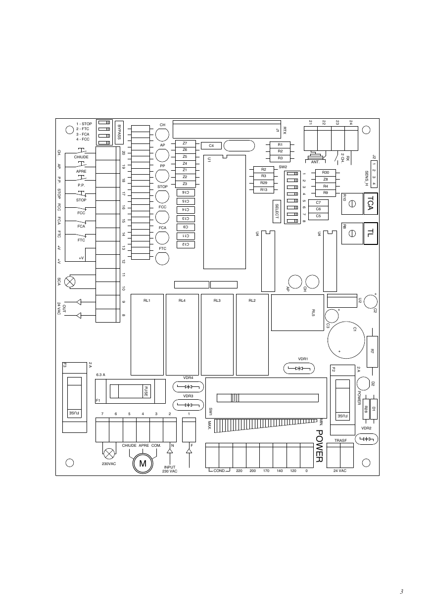
Schéma de la carte électronique
Italiano — Centralina a microprocessore per RI.6E
La centralina a microprocessore per ”RI.6E” può essere usata con motori di potenza non superiore a 500W.
La Regolazione della coppia del motore può essere effettuata tramite il commutatore a 5 posizioni ”POWER”. Tale commutatore deve essere messo nella posizione in cui opponendo una certa resistenza all’automatismo, una volta avviato possa essere fermato garantendo una certa sicurezza in caso di urto a cose e persone.
La Funzione di spunto permette di avere la massima coppia motore per circa 1 sec. all’avviamento dello stesso. Lo spunto può essere disattivato ponendo il Dip-Switch ”DSW5”= Off.
Consigli per l’installazione
- L’installazione elettrica e la logica di funzionamento devono essere in accordo con le normative vigenti.
- È consigliabile tenere i cavi di potenza (motore, alimentazione) separati da quelli di comando (pulsanti, fotocellule, radio); per evitare interferenze è preferibile prevedere ed utilizzare due guaine separate (vedi EN 60204-1 15.1.3).
- Ricontrollare tutti i collegamenti fatti prima di dare tensione.
- Controllare che le impostazioni dei Dip-Switch siano quelle volute.
- Dando tensione il led ”POWER” si deve illuminare, in caso contrario controllare l’integrità dei fusibili e la presenza di 230Vac, 50Hz tra i morsetti 1 e 2 (INPUT 230VAC - rispettare fase/neutro).
- Gli ingressi N.C. non utilizzati devono essere ponticellati con il comune ”+V”.
- Nel caso in cui il senso di rotazione del motore sia invertito basta invertire i fili ”APRE” - ”CHIUDE” del motore stesso e i fili dei finecorsa ”FCA” - ”FCC”.
Funzione Ingressi/Uscite
| Morsetti | Funzione |
|---|---|
| 1,2 | INPUT 230VAC= Alimentazione centralina 230Vac, 50Hz (rispettare fase/neutro) |
| 3,4,5 | COM/APRE/CHIUDE= Ai rispettivi morsetti del motore a 230Vac, 50Hz (è obbligatorio collegare il filo di Terra - giallo/verde sulla carcassa del motore) |
| 6,7 | LAMP230= Al lampeggiante a 230Vac |
| 8,9 | OUT 24VAC= Uscita alimentazione ausiliaria 24Vac (1A max.) |
| 10,11 | SCA= Contatto ”Spia cancello aperto” |
| 12,13 | +V= Comune a tutti gli ingressi di comando |
| 14 | FTC= Ingresso ricevitore fotocellula (contatto n.c.) |
| 15 | FCA= Ingresso finecorsa Apre (contatto n.c.) |
| 16 | FCC= Ingresso finecorsa Chiude (contatto n.c.) |
| 17 | STOP= Ingresso pulsante di STOP (contatto n.c.) |
| 18 | P.P.= Ingresso pulsante PASSO/PASSO (contatto n.o.) |
| 19 | APRE= Ingresso pulsante APRE (contatto n.o.) |
| 20 | CHIUDE= Ingresso pulsante CHIUDE (contatto n.o.) |
| 21,22 | ANT.= Ingresso antenna scheda radio |
| 23,24 | RX 2CH.= Contatto 2° canale scheda radio (contatto n.o.) |
| J2 | SENS_H= Ingresso per scheda antischiacciamento (opzionale) ”DA.AS”. pin 1-2: alimentazione 24Vdc (1 +; 2 -); pin 2-3: ingresso contatto n.c. (oppure per qualsiasi altro dispositivo di sicurezza n.c.). L’intervento del dispositivo provoca l’arresto o l’inversione di marcia del motore. Se non vengono utilizzati i pin 2 e 3 devono essere ponticellati. |
Funzionamento dell’uscita ”Spia cancello aperto”
- Se il cancello è chiuso (intervento finecorsa di chiusura - fine del tempo di lavoro in chiusura), la spia è spenta.
- Se il motore è in fase di apertura, la spia lampeggia lentamente (1Hz circa).
- Se il motore è in fase di chiusura, la spia lampeggia velocemente (2Hz circa).
- Se il cancello è aperto o la corsa viene interrotta manualmente (P.P. - STOP), la spia rimane accesa.
N.B.: La spia è comandata da un relé. Le commutazioni sono quindi di solito udibili durante il funzionamento normale della centrale.
Funzione Dip-Switch ”Select”
N.B.: Ogni cambio di funzione deve essere eseguito in assenza di tensione.
| Dip | Off | On |
|---|---|---|
| DSW1 — Funzionamento ”Pulsante P.P.” e telecomando | APRE - STOP - CHIUDE | APRE - CHIUDE - APRE |
| DSW2 — Richiusura automatica (Trimmer TCA) | Abilitata | Disabilitata |
| DSW3 — Funzione condominiale | Disabilitata | Abilitata |
| DSW4 — Prelampeggio | Disabilitato | Abilitato |
| DSW5 — Spunto motore | Disabilitato | Abilitato |
| DSW6 — Intervento ingresso ”FTC” in apertura | Nessun intervento | Stop temporaneo |
| DSW7 — Funzionamento ingresso ”APRE” | Pulsante APRE | Pulsante PEDONALE |
| DSW8 — Sensore SENS_H | Abilitato in apertura e chiusura | Abilitato solo in chiusura |
Funzione Dip-Switch ”Bypass”
I dip-switch ”Bypass” consentono di escludere gli ingressi normalmente chiusi che non si desidera utilizzare.
| Dip | Off | On |
|---|---|---|
| DSW1 — Ingresso Stop | Abilitato | Disabilitato |
| DSW2 — Ingresso FTC | Abilitato | Disabilitato |
| DSW3 — Ingresso FCA | Abilitato | Disabilitato |
| DSW4 — Ingresso FCC | Abilitato | Disabilitato |
Funzione dei Trimmer
- TCA — Regola il tempo di richiusura automatica quando è abilitata (DSW2= Off). La regolazione varia da 10 sec. a 200 sec. Il tempo minimo si ottiene ruotando il trimmer tutto in senso antiorario.
- TL — Regola il tempo di lavoro dell’automatismo oltre il quale interverrà la protezione software nel caso in cui i finecorsa si guastassero (posizionarlo circa 4 sec. in più del tempo di corsa effettiva). La regolazione varia da 10 sec. a 200 sec.; tempo minimo ruotando il trimmer tutto in senso antiorario.
English — Control unit with microcontroller for RI.6E
The control unit with microcontroller for RI.6E is suitable for motors with up to 500W power.
The Adjustment of the motor torque can be carried out using the 5-position ”POWER” switch. This switch should be placed in the position in which, once the automation has started, it can be stopped if it comes up against a certain amount of resistance. This acts as a safety function to protect people or things from impact.
The Starting function allows the maximum motor torque to be obtained for about 1 second when the motor is started. This starting function can be deactivated by positioning the DSW5 Dip-Switch on OFF.
Installation instructions
- The electrical installation and functioning logic must comply with current standards.
- Keep the power cables (for the motor and power supply) away from the control cables (buttons, photocells, radio). To avoid interference use two separate sheaths (see EN 60204-1 15.1.3).
- Check all the connections again before supplying voltage.
- Check that the Dip-Switch settings are as required.
- When voltage is supplied, the ”POWER” led should light up. If not, check the state of the fuses and whether 230Vac, 50Hz power is present between terminals 1 and 2 (INPUT 230VAC - respect phase/neutral wire position).
- The N.C. inputs not used must be connected to the common ”+V”.
- If the direction of the motor rotation is not correct, invert the ”OPEN” - ”CLOSE” wires of the motor as well as the wires of the ”FCA” - ”FCC” limit switches.
Input/Output functions
| Terminals | Function |
|---|---|
| 1,2 | INPUT 230VAC= Control unit 230Vac, 50Hz power supply (respect phase/neutral wire position) |
| 3,4,5 | COM/APRE/CHIUDE= Connection to the corresponding 230Vac, 50Hz motor terminals (the earth wire green/yellow must be connected to the motor housing) |
| 6,7 | LAMP230= Connection to the 230Vac blinker |
| 8,9 | OUT 24VAC= 24Vac auxiliary power supply output (1A max.) |
| 10,11 | SCA= ”Gate open warning light” contact |
| 12,13 | +V= Common connection to all the control inputs |
| 14 | FTC= Photocell receiver input (n.c. contact) |
| 15 | FCA= Limit switch input - Opening (n.c. contact) |
| 16 | FCC= Limit switch input - Closing (n.c. contact) |
| 17 | STOP= STOP button input (n.c. contact) |
| 18 | P.P.= STEP-by-STEP button input (n.o. contact) |
| 19 | APRE= OPEN button input (n.o. contact) |
| 20 | CHIUDE= CLOSE button input (n.o. contact) |
| 21,22 | ANT.= Input of radio board antenna |
| 23,24 | RX 2CH.= Radio board 2nd channel contact (n.o. contact) |
| J2 | SENS_H= Input for optional anti-crash card ”DA.AS”. 1-2 pin: 24Vdc power supply (1 +; 2 -); 2-3 pin: n.c. contact input (or for any other n.c. safety device). The activation of the device causes the stopping or the reversion movement of the motor. Pins 2 and 3 must be short-circuited if not in use. |
Functioning for the ”Gate open warning light” contact
- If the gate is closed, the warning light is turned off.
- If the gate is opening, the warning light flashes slow (about 1Hz).
- If the gate is closing, the warning light flashes fast (about 2Hz).
- If the gate is open or the race is interrupted manually (P.P. - STOP), the warning light remains turned on.
N.B.: The led is driven by a relay, thus the commutation can be normally heard during the normal function of the control board.
”Select” dip-switch functions
N.B.: Every change of functions have to be done without electricity.
| Dip | Off | On |
|---|---|---|
| DSW1 — P.P. button and Remote control | OPEN - STOP - CLOSE | OPEN - CLOSE - OPEN |
| DSW2 — Automatic re-closing (TCA Trimmer) | Enabled | Disabled |
| DSW3 — Apartment building function | Disabled | Enabled |
| DSW4 — Pre-blinking | Disabled | Enabled |
| DSW5 — Motor starting function | Disabled | Enabled |
| DSW6 — ”FTC” input intervention on opening | No intervention | Temporary stop |
| DSW7 — ”OPEN” input functioning | OPEN button | PEDESTRIAN button |
| DSW8 — SENS_H sensor | Enabled in both opening and closing | Enabled only in closing |
”By-pass” dip-switch function
The ”By-pass” dip-switches allow to exclude the normally closed inputs which are not in use.
| Dip | Off | On |
|---|---|---|
| DSW1 — Input Stop | Enabled | Disabled |
| DSW2 — Input FTC | Enabled | Disabled |
| DSW3 — Input FCA | Enabled | Disabled |
| DSW4 — Input FCC | Enabled | Disabled |
Trimmer functions
- TCA — Allows the automatic re-closing time to be adjusted when enabled (DSW2 on OFF). Adjustment from a minimum of 10 to a maximum of 200 seconds. Minimum time obtained by rotating the trimmer completely anticlockwise.
- TL — Allows the working time of the automation to be adjusted. If the limit switches fail, the software protection will intervene after this time has elapsed (add about 4 sec. to the actual stroke time). Adjustment from 10 to 200 seconds; minimum time by rotating the trimmer completely anticlockwise.
Deutsch — Mikrocontroller-Steuerung für ”RI.6E”
Die Mikrocontroller-Steuerung für “RI.6E” kann mit Motoren mit einer Leistung nicht über 500W verwendet werden.
Die Einstellung des Motordrehmomentes kann anhand eines 5-Weg-Schalters ”POWER” ausgeführt werden. Dieser Schalter muß so positioniert werden, daß er, einmal angefahren, bei einem gewissen Widerstand gegen den Antrieb angehalten werden kann und eine gewisse Sicherheit im Fall von Stoßen von Gegenständen oder Personen garantiert.
Die Anlauffunktion erlaubt, einen max. Motordrehmoment für ca. 1 Sek. ab Anfahren desselben zu haben. Das Anlaufen kann durch Stellen der DIP-Drucktaste ”DSW5”= Off deaktiviert werden.
Empfehlungen für den Einbau
- Der elektrische Einbau sowie die Funktionslogistik müssen mit den geltenden Richtlinien im Einklang sein.
- Wir empfehlen, die Stromkabel (Motor, Zufuhr) von den Steuerkabeln (Drucktasten, Lichtschranken, Empfänger) unterscheidbar zu halten; um Störungen zu vermeiden zwei getrennte Kabelmäntel vorsehen (siehe EN 60204-1 15.1.3).
- Sämtliche gemachten Anschlüsse vor der Stromzugabe erneut überprüfen.
- Überprüfen, ob die Einstellungen der DIP-Drucktasten den gewünschten entsprechen.
- Bei Stromzugabe muß die LED-Diode “POWER” leuchten. Falls nicht, überprüfen, ob die Sicherungen ganz sind und ob zwischen den Klemmen 1 und 2 (INPUT 230VAC - Phase/Neutral beachten) 230Vac, 50Hz gegeben ist.
- Die N.C. Eingaben, die nicht verwendet werden, mit dem Mittelleiter ”+V” überbrücken.
- Falls die Drehrichtung des Motors vertauscht ist, die Drähte “ÖFFNET” - “SCHLIESST” des Motors und die Drähte des Endschalters “FCA” - “FCC” vertauschen.
Funktion Eingaben/Ausgaben
| Klemmen | Funktion |
|---|---|
| 1,2 | INPUT 230VAC= Zufuhr Steuerung 230Vac 50Hz (Phase/Neutral beachten) |
| 3,4,5 | COM/APRE/CHIUDE= An die entsprechenden Motorklemmen 230Vac 50Hz. Erdleiter (gelb/grün) mit dem Motorgehäuse verbinden |
| 6,7 | LAMP230= An 230Vac Blinkleuchte |
| 8,9 | OUT 24VAC= Ausgabe Hilfszufuhr 24Vac (max. 1A) |
| 10,11 | SCA= Kontakt ”Torblinker Auf” |
| 12,13 | +V= Gemeinsam bei allen Steuereingaben |
| 14 | FTC= Eingabe Lichtschrankenempfänger (Ruhekontakt) |
| 15 | FCA= Eingabe Endschalter Öffnet (Ruhekontakt) |
| 16 | FCC= Eingabe Endschalter Schließt (Ruhekontakt) |
| 17 | STOP= Eingabe STOP-Drucktaste (Ruhekontakt) |
| 18 | P.P.= Eingabe SCHRITT/SCHRITT-Drucktaste (Arbeitskontakt) |
| 19 | APRE= Eingabe ÖFFNET-Drucktaste (Arbeitskontakt) |
| 20 | CHIUDE= Eingabe SCHLIESST-Drucktaste (Arbeitskontakt) |
| 21,22 | ANT.= Eingabe Antenne Empfängersteckkarte |
| 23,24 | RX 2CH.= Kontakt 2. Kanal Empfängersteckkarte (Arbeitskontakt) |
| J2 | SENS_H= Eingang für quetschbeständige Karte (Option) ”DA.AS”. Pin 1-2: Speisung 24Vdc (1 +; 2 -); Pin 2-3: Eingang Kontakt n.c. (oder für jede andere n.c. Sicherheitsvorrichtung). Das Einschalten hält den Motor an oder schaltet um. Wenn Pin 2 und 3 nicht verwendet werden, sind sie zu überbrücken. |
Funktion des Ausgangs "Meldeleuchte für offenes Tor"
- Wenn das Tor geschlossen ist, ist die Meldeleuchte ausgeschaltet.
- Wenn der Motor das Tor öffnet, blinkt die Meldeleuchte langsam (1Hz circa).
- Wenn der Motor das Tor schließt, blinkt die Meldeleuchte schnell (2Hz circa).
- Wenn das Tor geöffnet ist oder die Bewegung von Hand unterbrochen wird (P.P. - STOP), leuchtet die Meldeleuchte weiter.
N.B.: Die Meldeleuchte wird über ein Relais gesteuert. Das Umschalten ist folglich beim normalen Betrieb der Zentrale hörbar.
”Select” Funktion der Dip-Drucktasten
Anmerkung: Alle Funktionsänderung muß in Mangel von Spannung verricht werden.
| Dip | Off | On |
|---|---|---|
| DSW1 — P.P.-Drucktaste und Fernsteuerung | ÖFFNET - STOP - SCHLIESST | ÖFFNET - SCHLIESST - ÖFFNET |
| DSW2 — Automatische Wiederschließung (Trimmer TCA) | Aktiviert | Deaktiviert |
| DSW3 — Mehrfamilienhaus-Funktion | Deaktiviert | Aktiviert |
| DSW4 — Vorblinkleuchte | Deaktiviert | Aktiviert |
| DSW5 — Motoranlaufen | Deaktiviert | Aktiviert |
| DSW6 — Eingabe ”FTC” bei Öffnung | Kein Eingriff | Vorübergehend Stop |
| DSW7 — Eingabe ”ÖFFNET” | Drucktaste ÖFFNET | Drucktaste FUSSGÄNGER |
| DSW8 — Sensor SENS_H | Beim Öffnen und Schließen freigegeben | Nur beim Schließen freigegeben |
”Bypass” Funktion der Dip-Drucktasten
Die Dip-Schalter ”Bypass” ermöglichen es die Ruhekontakte am Eingang, die nicht gewünscht werden, auszuschließen.
| Dip | Off | On |
|---|---|---|
| DSW1 — Eingang Stop | Eingang frei | Eingang gesperrt |
| DSW2 — Eingang FTC | Eingang frei | Eingang gesperrt |
| DSW3 — Eingang FCA | Eingang frei | Eingang gesperrt |
| DSW4 — Eingang FCC | Eingang frei | Eingang gesperrt |
Funktion der Trimmer
- TCA — Wenn aktiviert, erlaubt er die Einstellung der automatischen Wiederschließzeit (DSW2 = Off). Die Einstellung variiert von min. 10 bis max. 200 Sek. Die Minimalzeit erhält man durch Drehen des Trimmers gegen den Uhrzeigersinn.
- TL — Erlaubt die Einstellung der Antriebbetriebszeit, über die die Software-Sicherung eingreift, falls die Endschalter beschädigt sein sollten (auf ca. 4 Sek. länger als die effektive Laufzeit stellen). Einstellung von min. 10 bis max. 200 Sek.; Minimalzeit durch Drehen gegen den Uhrzeigersinn.
Français — Centrale à microcontrôleur pour ”RI.6E”
La centrale à microcontrôleur pour “RI.6E” peut être utilisée avec des moteurs ayant une puissance non supérieure à 500W.
Le Réglage du couple du moteur peut être effectué au moyen du commutateur à 5 positions ”POWER”. Ce commutateur doit être mis dans la position où, en opposant une certaine résistance à l’automatisme, une fois mis en marche il puisse être arrêté en garantissant une certaine sécurité en cas de choc contre des personnes ou des choses.
La Fonction de décollage permet d’avoir le couple maximum du moteur pendant environ 1 s à sa mise en fonction. Le décollage peut être désactivé en plaçant l’interrupteur DIP ”DSW5” sur Off.
Conseils pour l’installation
- L’installation électrique et la logique de fonctionnement doivent être conformes aux normes en vigueur.
- Il est conseillé de maintenir les câbles de puissance (moteur, alimentation) séparés de ceux de commande (touches, cellules photoélectriques, radio) ; afin d’éviter des interférences, il est préférable de prévoir et d’utiliser deux gaines séparées (voir EN 60204-1 15.1.3).
- Recontrôler toutes les connexions effectuées avant d’appliquer la tension.
- S’assurer que les réglages des interrupteurs DIP soient corrects.
- En appliquant la tension, la DEL “POWER” doit s’allumer ; si cela n’était pas le cas, contrôler le bon fonctionnement des fusibles et la présence des 230Vca, 50Hz entre les bornes 1 et 2 (INPUT 230Vca - respecter phase/neutre).
- Réaliser un pontet entre les entrées N.C. pas utilisées et le commun “+V”.
- Si le sens de rotation du moteur est inversé, il suffit d’inverser les fils “OUVRE” - “FERME” du moteur et les fils des fin de course “FCA” - “FCC”.
Fonction Entrées/Sorties
| Bornes | Fonction |
|---|---|
| 1,2 | INPUT 230VAC= Alimentation centrale 230Vca, 50Hz (respecter phase/neutre) |
| 3,4,5 | COM/APRE/CHIUDE= Aux bornes correspondantes du moteur 230Vca, 50Hz (il est obligatoire de connecter le fil de terre jaune/vert à la carcasse du moteur) |
| 6,7 | LAMP230= Au feu clignotant à 230Vca |
| 8,9 | OUT 24VAC= Sortie alimentation auxiliaire 24Vca (1A maxi) |
| 10,11 | SCA= Contact ”Témoin portail ouvert” |
| 12,13 | +V= Commun à toutes les entrées de commande |
| 14 | FTC= Entrée récepteur cellule photoélectrique (contact n.f.) |
| 15 | FCA= Entrée fin de course Ouvre (contact n.f.) |
| 16 | FCC= Entrée fin de course Ferme (contact n.f.) |
| 17 | STOP= Entrée touche STOP (contact n.f.) |
| 18 | P.P.= Entrée touche PAS à PAS (contact n.o.) |
| 19 | APRE= Entrée touche OUVRE (contact n.o.) |
| 20 | CHIUDE= Entrée touche FERME (contact n.o.) |
| 21,22 | ANT.= Entrée antenne carte radio |
| 23,24 | RX 2CH.= Contact 2e canal carte radio (contact n.o.) |
| J2 | SENS_H= Entrée pour carte anti-écrasement (en option) ”DA.AS”. pins 1-2 : alimentation 24Vcc (1 +; 2 -) ; pins 2-3 : entrée contact n.f. (ou pour n’importe quel autre dispositif de sécurité n.f.). L’intervention du dispositif provoque l’arrêt et l’inversion de marche du moteur. En cas de non-utilisation des pins 2 et 3, ceux-ci devront être reliés par un pontet. |
Fonctionnement de la sortie ”Voyant portail ouvert”
- Si le portail est fermé (intervention fin de course de fermeture – fin du temps de travail en fermeture), le voyant est éteint.
- Si le moteur est en ouverture, le voyant clignote lentement (1Hz environ).
- Si le moteur est en fermeture, le voyant clignote rapidement (2Hz environ).
- Si le portail est ouvert ou la course est interrompue manuellement (P.P. - STOP), le voyant demeure allumé.
N.B.: Le voyant est commandé par un relais. Les commutations sont donc seulement audibles durant le fonctionnement normal de la centrale.
Fonction dip-switch ”Select”
N.B.: Tous les échanges de fonction doivent être effectués dans l’absence de tension.
| Dip | Off | On |
|---|---|---|
| DSW1 — Touche P.P. et télécommande | OUVRE - STOP - FERME | OUVRE - FERME - OUVRE |
| DSW2 — Refermeture automatique (TCA) | Activée | Désactivée |
| DSW3 — Fonction ensembles collectifs d’habitation | Désactivée | Activée |
| DSW4 — Préclignotement | Désactivé | Activé |
| DSW5 — Décollage du moteur | Désactivé | Activé |
| DSW6 — Entrée ”FTC” en ouverture | Aucune intervention | Stop provisoire |
| DSW7 — Entrée ”OUVRE” | Touche OUVRE | Touche PIÉTONNIÈRE |
| DSW8 — Capteur SENS_H | Validé en ouverture et fermeture | Validé seulement en fermeture |
Fonction dip-switch ”Bypass”
Les dip-switch ”Bypass” consentent d’exclure les entrées normalement fermées que l’on ne désire pas utiliser.
| Dip | Off | On |
|---|---|---|
| DSW1 — Entrée Stop | Entrée validée | Entrée invalidée |
| DSW2 — Entrée FTC | Entrée validée | Entrée invalidée |
| DSW3 — Entrée FCA | Entrée validée | Entrée invalidée |
| DSW4 — Entrée FCC | Entrée validée | Entrée invalidée |
Fonction des potentiomètres
- TCA — Permet de régler le temps de refermeture automatique, si elle est activée (DSW2 sur Off). Le réglage varie d’un minimum de 10 s. jusqu’à un maximum de 200 s. Le temps minimum s’obtient en tournant le potentiomètre complètement dans le sens inverse des aiguilles d’une montre.
- TL — Permet de régler le temps de travail de l’automatisme après lequel la protection du logiciel interviendra si les fin de course présentent une défaillance (le placer à 4 s. en plus du temps de course effectif). Le réglage varie de 10 s. à 200 s. ; le temps minimum s’obtient en tournant le potentiomètre dans le sens inverse des aiguilles d’une montre.
Español — Centralita a microprocesador por ”RI.6E”
La centralita a microprocesador por “RI.6E” puede ser usada con motores de potencia no superior a 500W.
La Regulación de la fuerza del motor puede ser efectuada mediante el conmutador de 5 posiciones ”POWER”. Tal conmutador debe estar puesto en la posición en la cual, oponiendo una cierta resistencia al automatismo, una vez puesto en marcha, pueda ser parado garantizando una cierta seguridad en caso de golpe a personas o cosas.
La Función de despunte permite tener la máxima potencia del motor durante aproximadamente 1 segundo en la arrancada del mismo. El despunte puede ser desactivado poniendo el Dip-Switch ”DSW5”= Off.
Consejos para la instalación
- La instalación eléctrica y la lógica de funcionamiento deben estar de acuerdo con la normativa vigente.
- Es aconsejable tener los cables de potencia (motor, alimentación) separados de los de mando (pulsadores, fotocélulas, radio); para evitar interferencias es preferible preveer y utilizar dos tubos separados (véase EN 60204-1 15.1.3).
- Repasar todas las conexiones hechas antes de dar tensión.
- Controlar que el posicionamiento de los Dip-Switch sean los deseados.
- Dando tensión el led ”POWER” se debe iluminar, en caso contrario comprobar la integridad de los fusibles y la presencia de 230Vac, 50Hz entre los bornes 1 y 2 (INPUT 230VAC - respetar fase/neutro).
- Las entradas N.C. no utilizadas deben ser puenteadas con el común ”+V”.
- En caso de que el sentido de rotación del motor esté invertido, basta con invertir los cables ”APRE” - ”CHIUDE” del propio motor y los cables de los finales de carrera ”FCA” - ”FCC”.
Función Entradas / Salidas
| Bornes | Función |
|---|---|
| 1,2 | INPUT 230 VAC= Alimentación centralita 230Vac 50 Hz (respetar fase/neutro) |
| 3,4,5 | COM/APRE/CHIUDE= A los respectivos bornes motor 230Vac 50 Hz. Es obligatorio conectar el cable de tierra amarillo/verde a la carcasa del motor |
| 6,7 | LAMP 230= Al relampagueador a 230Vac |
| 8,9 | OUT 24VAC= Salida alimentación auxiliar 24Vac (1A máximo) |
| 10,11 | SCA= Contacto ”Piloto cancela abierta” |
| 12,13 | +V= Común para todas las entradas de mando |
| 14 | FTC= Entrada receptor fotocélula (contacto n.c.) |
| 15 | FCA= Entrada final de carrera Abre (contacto n.c.) |
| 16 | FCC= Entrada final de carrera Cierra (contacto n.c.) |
| 17 | STOP= Entrada pulsador de STOP (contacto n.c.) |
| 18 | P.P.= Entrada pulsador PASO A PASO (contacto n.o.) |
| 19 | APRE= Entrada pulsador ABRE (contacto n.o.) |
| 20 | CHIUDE= Entrada pulsador CIERRA (contacto n.o.) |
| 21,22 | ANT.= Entrada antena tarjeta radio |
| 23,24 | RX 2CH.= Contacto 2° canal tarjeta radio (contacto n.o.) |
| J2 | SENS_H= Entrada para tarjeta antiaplastamiento (opción) ”DA.AS”. pin 1-2: Alimentación 24Vcc (1 +; 2 -); pin 2-3: Entrada contacto n.c. (o para cualquier otro dispositivo de seguridad n.c.). La intervención del dispositivo ocasiona la parada o la inversión de la marcha del motor. Si no se usan los pin 2 y 3 es menester puentearlos. |
Funcionamiento de la salida ”Chivato verja abierta”
- Si la verja está cerrada (actuación del final de carrera de cierre - fin del tiempo de trabajo en cierre), el chivato está apagado.
- Si el motor está en fase de apertura, el chivato parpadea despacio (1Hz aprox.).
- Si el motor está en fase de cierre, el chivato parpadea rápido (2Hz aprox.).
- Si la verja está abierta o la carrera es interrumpida manualmente (P.P. - STOP), el chivato queda encendido.
N.B.: El chivato está controlado por un relé. Las conmutaciones normalmente se pueden pues oír durante el funcionamiento normal de la central.
Función Dip-Switch ”Select”
Nota: Para cambio de función debe ser realizado en ausencia de tensión.
| Dip | Off | On |
|---|---|---|
| DSW1 — Pulsador P.P. y radiomando | APRE - STOP - CHIUDE | APRE - CHIUDE - APRE |
| DSW2 — Cierre automático (Trimmer TCA) | Habilitado | Deshabilitado |
| DSW3 — Función comunitaria | Deshabilitada | Habilitada |
| DSW4 — Pre-relampagueo | Deshabilitado | Habilitado |
| DSW5 — Despunte del motor | Deshabilitado | Habilitado |
| DSW6 — Entrada ”FTC” en apertura | Ninguna intervención | Stop temporal |
| DSW7 — Entrada ”APRE” | Pulsador APRE | Pulsador PEDONALE |
| DSW8 — Sensor SENS_H | Habilitado para apertura y cierre | Habilitado sólo para el cierre |
Función dip-switch ”Bypass”
Los dip-switch ”Bypass” permiten excluir las entradas normalmente cerradas que no se desea emplear.
| Dip | Off | On |
|---|---|---|
| DSW1 — Entrada Stop | Habilitada | Inhabilitada |
| DSW2 — Entrada FTC | Habilitada | Inhabilitada |
| DSW3 — Entrada FCA | Habilitada | Inhabilitada |
| DSW4 — Entrada FCC | Habilitada | Inhabilitada |
Función de los Trimmer
- TCA — Permite regular el tiempo de cierre automático cuando está habilitado (DSW2= Off). La regulación varía desde un mínimo de 10 segundos hasta un máximo de 200 segundos. El tiempo mínimo se obtiene girando el trimmer totalmente en sentido antihorario.
- TL — Permite regular el tiempo de trabajo del automatismo, tras el que intervendrá la protección del software en el caso que los finales de carrera se averiasen (posicionando aproximadamente 4 segundos más del tiempo de desplazamiento efectivo). La regulación varía de 10 a 200 segundos; tiempo mínimo girando el trimmer en sentido antihorario.
Polski — Centralka z mikroprocesorem dla RI.6E
Centralka z mikroprocesorem dla „RI.6E” może być stosowana z silnikiem o mocy nie wyższej niż 500W.
Regulacji momentu obrotowego silnika można dokonywać za pomocą 5 stopniowego przełącznika „POWER”. Przełącznik ten musi być ustawiony w takiej pozycji w której, stawiając odpowiedni opór posuwającemu się automatyzmowi, będzie w stanie go zatrzymać, gwarantując odpowiednie bezpieczeństwo rzeczom i osobom podczas zderzenia.
Funkcja skokowa umożliwia osiągnięcie maksymalnego momentu obrotowego silnika na czas około 1 sek. podczas rozruchu. Skok może zostać wyłączony przez przełączenie Dip-Switch na „DSW5”= Off.
Wskazówki dla instalacji
- Instalacja elektryczna i logika jej funkcjonowania muszą być zgodne z obowiązującymi normami.
- Zaleca się oddzielne trzymanie przewodów mocy (silnik, zasilanie prądem) i przewodów sterowania (przyciski, fotokomórki, radio); dla uniknięcia interferencji najlepiej jest stosować dwie różniące się osłony kabla (zobacz EN 60204-1 15.1.3).
- Przed włączeniem prądu należy sprawdzić wszystkie dokonane podłączenia.
- Sprawdzić czy zostały ustawione właściwe Dip-Switch.
- Po podłączeniu napięcia led „Power” powinien się zaświecić, w przeciwnym razie należy sprawdzić stan bezpieczników i występowanie napięcia 230Vac, 50Hz między zaciskami 1 i 2 (INPUT 230Vac - przestrzegać faza/zerowy).
- Nie używane wejścia N.C. należy mostkować ze wspólnym „+V”.
- W przypadku gdy ulegnie zmianie kierunek obrotów silnika, wystarczy przestawić przewody „APRE” (OTWORZY) - „CHIUDE” (ZAMKNIE) samego silnika oraz przewody krańcowych wyłączników posuwu „FCA” - „FCC”.
Funkcja WEJŚĆ / WYJŚĆ
| Zaciski | Funkcja |
|---|---|
| 1,2 | INPUT 230VAC= Zasilanie centralki 230Vac, 50Hz (przestrzegać faza/zerowy) |
| 3,4,5 | COM/OTWORZY/ZAMKNIE= Dla odpowiednich zacisków silnika na 230Vac, 50Hz (obowiązkowo podłączyć przewód uziemiający żółto/zielony do kadłuba silnika) |
| 6,7 | LAMP230= Dla światła migającego na 230Vac |
| 8,9 | OUT24VAC= Wyjście dla zasilania pomocniczego 24Vac (1A max) |
| 10,11 | SCA= Sygnalizowanie otwarcia bramy |
| 12,13 | +V= Wspólny dla wszystkich wejść układu sterującego |
| 14 | FTC= Wejście dla odbiornika fotokomórki (styk n.c.) |
| 15 | FCA= Wejście dla krańcowego wyłącznika posuwu podczas Otwierania (styk n.c.) |
| 16 | FCC= Wejście dla krańcowego wyłącznika posuwu podczas Zamykania (styk n.c.) |
| 17 | STOP= Wejście dla przycisku STOP (styk n.c.) |
| 18 | P.P.= Wejście dla przycisku POSUW/POSUW (styk n.o.) |
| 19 | APRE= Wejście dla przycisku OTWORZY (styk n.o.) |
| 20 | CHIUDE= Wejście dla przycisku ZAMKNIE (styk n.o.) |
| 21,22 | ANT.= Wejście dla anteny modułu radiowego |
| 23,24 | RX 2CH.= Połączenie 2-go kanału modułu radiowego (styk n.o.) |
| J2 | SENS_H= Wejście dla modułu przeciwzgniecenia (fakultatywne) DA.AS. pin 1-2 zasilanie 24Vac (1+; 2 -); pin 2-3 wejście dla styku n.c. (lub dla każdego innego urządzenia zabezpieczającego). Włączenie się urządzenia powoduje zatrzymanie silnika lub zmianę kierunku jego obrotów. Jeżeli pin 2-3 nie będą używane należy wykonać mostek. |
Funkcjonowanie wyjścia „Kontrolka otwarcia bramy”
- Przy zamkniętej bramie (włączenie się krańcowego wyłącznika posuwu - po upływie czasu na zamykanie) kontrolka nie świeci się.
- Kiedy silnik pracuje w fazie otwierania, kontrolka miga wolno (około 1Hz).
- Kiedy silnik pracuje w fazie zamykania, kontrolka miga szybko (około 2Hz).
- Zarówno przy otwartej bramie jak i przy ręcznym zatrzymaniu posuwu (P.P. - STOP), kontrolka świeci się światłem ciągłym.
Uwaga: Kontrolka sterowana jest przez osobny przełącznik. Komutacje są więc słyszalne zazwyczaj podczas normalnego funkcjonowania centralki.
Funkcja Dip-Switch „Select”
Uwaga: Każdorazowa zmiana funkcji może być dokonywana wyłącznie po odłączeniu napięcia.
| Dip | Off | On |
|---|---|---|
| DSW1 — Przycisk P.P. i Pilot | OTWORZY - STOP - ZAMKNIE | OTWORZY - ZAMKNIE - OTWORZY |
| DSW2 — Samoczynne zamykanie (Trimmer TCA) | Włączone | Wyłączone |
| DSW3 — Funkcja współużytkowa | Wyłączona | Włączona |
| DSW4 — Funkcja ostrzegawcza (światło migające) | Wyłączone | Włączone |
| DSW5 — Skok silnika | Wyłączony | Włączony |
| DSW6 — Wejście „FTC” podczas otwierania | Brak interwencji | Zatrzymanie chwilowe |
| DSW7 — Wejście „OTWORZY” | przycisk OTWORZY | przycisk NOŻNY |
| DSW8 — Czujnik SENS_H | Włączone dla otwierania i zamykania | Włączone tylko dla zamykania |
Funkcja Dip-Switch „Bypass”
Dip-Switch „Bypass” umożliwiają eliminację wejść zazwyczaj zamkniętych, których nie zamierza się używać.
| Dip | Off | On |
|---|---|---|
| DSW1 — Wejście Stop | Włączone | Wyłączone |
| DSW2 — Wejście FTC | Włączone | Wyłączone |
| DSW3 — Wejście FCA | Włączone | Wyłączone |
| DSW4 — Wejście FCC | Włączone | Wyłączone |
Funkcja Trimmerʼów
- TCA — Przy włączonej czynności, umożliwia regulowanie czasu samoczynnego zamykania poprzez ustawienie Dip-Switch na „DSW2”= Off. Zasięg regulacji: od minimum 10 sek. do maksymum 200 sek. Czas minimalny uzyskuje się poprzez pokręcanie potencjometrem w kierunku odwrotnym do ruchu wskazówek zegara.
- TL — Umożliwia regulowanie czasu pracy automatyzmów powyżej którego włączy się zabezpieczenie dla software w przypadku awarii krańcowych wyłączników posuwu (nastawiony czas musi być dłuższy o 4 sek. od czasu efektywnego posuwu). Zasięg regulacji: od minimum 10 sek. do maksymum 200 sek. Czas minimalny — pokręcając potencjometrem w kierunku odwrotnym do ruchu wskazówek zegara.